
SECTION 9
STEERING
FIGURE 9-64.
FIGURE 9-65.
surfaces into contact to allow splines to
engage (see figure 9-64). Torque capscrews per
specification (see figure 9-65).
9-47. INSTALLATION.
a. Position the power steering control unit in
the dashboard mounting (see figure 9-6).
b. Install the two (2) mounting capscrews
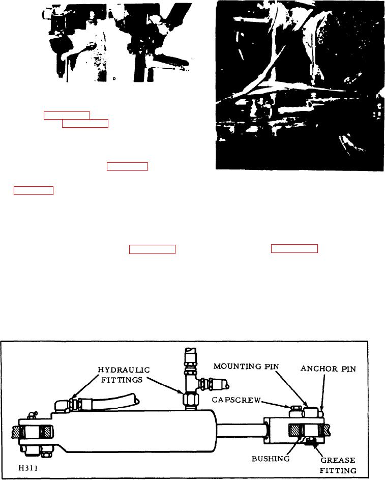
FIGURE 9-66.
(SW figure 9-5).
connected to the front frame.
c. Connect the four (4) hydraulic hoses to
their respective fittings as previously marked
4-52. Since the two cylinders are identical, the
during removal. Tighten connections to prevent
following instructions apply to both cylinders.
leakage.
9-54.
REMOVAL (see figure 9-67).
9-48.
STEERING CYLINDERS (see figure 9-66).
a. Disconnect the hydraulic lines and plug or
9-49. GENERAL.
cap the openings to keep out dirt and reduce
loss of oil.
9-50. Two double-acting hydraulic cylinders,
one on each side of the unit, are connected to
b. Remove the capscrews and anchor pins
each other so that when one extends, the other
from both ends of the cylinder.
retracts and vice versa.
c. Slide out both mounting pins and remove
9 - 5 1 . The rod ends of the cylinders are
the cylinder.
connected to the hitch and the bodies are
FIGURE 9-67.
9-13.