
SECTION 9
STEERING
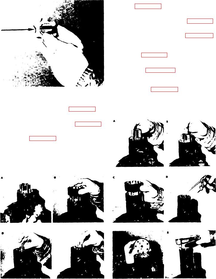
The valleys of both meter gear stars must
match (see figure 9-58).
y. Place the long spacer in position within
the end of the meter gear star (see figure 9-59).
z. Place the meter gear ring on the assembly
so that the bolt holes align (see figure 9-60).
aa. Pour a small quantity of Type "A"
transmission oil in each valley of the meter
gear star (see figure 9-61).
bb. Place the meter end cap over the
assembly (see figure 9-62) and install two
capscrews, finger tight, to maintain alignment
of the parts. Install all seven (7) capscrews and
bring them gradually and evenly to torque
specifications (see figure 9-63).
FIGURE 9-53.
cc. Check the condition of the column
assembly, clean it, and replace on the unit
u. Place the meter gear ring on the assembly
with two (2) capscrews oriented as before.
so that the bolt holes align (see figure 9-55).
Rotate the steering shaft while bringing the
v. Place the small spacer in position within
the end of the meter gear star (see figure 9-56).
w. Place the splined spacer in the meter
gear star (see figure 9-57). If the splined spacer
does not drop half way into the meter gear star
(that is, one row of splined teeth in the gear
and one row above the gear), the drive has not
properly engaged the cross pin - RECHECK.
x. Place the second meter gear star on the
FIGURE 9-59.
FlGURE 9-58.
exposed splined teeth of the splined spacer.
FIGURE 9-61.
FIGURE 9-60.
FIGURE 9-55.
FIGURE 9-54.
FIGURE 9-63.
FIGURE 9-62.
FIGURE 9-56.
FIGURE 9-57.
9-12.