TM 5-3895-383-24
2.
Use Tool (A) to loosen the unit injector, then rotate the
unit injector to disengage the injector rack from the fuel
control linkage. Remove the unit injector. Be sure O-
ring seal (2) is on the unit injector.
NOTE:
The following steps are for the installation of the
unit injectors.
3.
Inspect the cylinder head sleeve to insure that the
injector
sealing
surface
(seat)
is
clean.
Use
4C-8712 Reamer to dress the seat area, prior to
installation of injector in the cylinder head. Refer to
Special
Instruction,
NEHS0675
for
instructions
concerning
the
reaming
procedure
and
sleeve
replacement.
4.
Check the condition of the O-ring seal (2) on the unit
injector. If the O-ring seal is damaged, use new pats for
replacement. Install the O-ring seal on the unit injector.
5.
Lubricate the O-ring seal (2) on the unit injector with
clean engine oil.
6.
Position the unit injector in the cylinder head assembly;
then rotate it to engage the injector rack with the fuel
control linkage. Push down on the top of the unit
injector so the O-ring seal (2) slides into the bore in the
cylinder head assembly. Be sure the unit injector is
seated properly before installing bolt (1) that holds it in
position. Do not use bolt (1) to pull the unit injector
down into the cylinder head assembly.
7.
Install bolt (1). Use a 9S-7354 Torque Wrench (or
equivalent), and Tool D to tighten bolts (1) into position.
Excessive torque can cause injector damage and/or
seizure. Tighten the bolts to a torque of 12 ± 3 N m (9 ±
2 lb-ft).
End By:
a.
install rocker shaft assemblies and push rods
b.
set the valve lash, perform injector synchronization
and make all necessary fuel adjustments. Refer to
the Systems Operation Testing & Adjusting Module
for information regarding these procedures.
Fuel Control Linkage
Remove & Install Fuel Control
Linkage 1257-010
Tools Needed
A
1U-6675
Injector Spring Compressor
6
*Part of the 9U-7305 Fuel System Adjusting Tool Group
Start By:
a.
remove rocker shaft assemblies and push rods
b.
disconnect governor linkage as indicated in the
governor remove and install story
NOTICE
Do not remove the fuel control linkage (or injector racks)
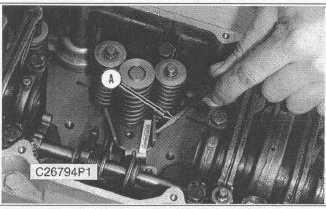
without having Tooling (A), the Injector Compressors,
installed. Damage to the injectors may occur. After
installing Tooling (A), tap on the top of each injector lightly
with a rubber mallet to prevent any binding or side loading
in the injectors.
1.
When removing the fuel control linkage with the
injectors in place install Tooling (A) on the unit injectors
and slightly compress the injector springs.
8-35


