TM 5-3895-383-24
Turbocharger
Remove & Install
Turbocharger 1052-010
Fluid Spillage Containment
Care must be taken to ensure that fluids are contained during
performance of inspection, maintenance, testing, adjusting and
repair of the machine. Be prepared to collect the fluid with
suitable containers before opening any compartment or
disassembling any component containing fluids. Refer to
"Tools And Shop Products Guide", NENG2500 for tools and
supplies suitable to collect and contain fluids in Caterpillar
machines. Dispose of fluids according to local regulations and
mandates.
NOTE:
The following steps are for the removal of the
turbocharger.
1.
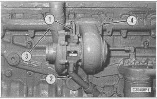
Disconnect oil supply tube assembly (1) from the
turbocharger.
2.
Disconnect oil drain tube assembly (2) from the
turbocharger.
3.
Loosen clamp (3).
4.
Remove four locknuts (4), the turbocharger and gasket
from the exhaust manifold.
5.
Remove end housings from the cartridge.
NOTE:
Place alignment marks on the turbocharger
cartridge and housings. Alignment marks will be
used during assembly.
NOTE:
Turbocharger is serviceable at cartridge level
only,
or
replacement
of
the
complete
turbocharger. Internal pads are not serviced.
NOTE:
For waste-gate type turbochargers, the waste-gate
mechanism is part of the turbine housing
assembly and is pre-set at the factory. There are
no adjustments or serviceable parts of the waste-
gate mechanism.
NOTE:
The following steps are for the installation of the
turbocharger.
6.
Check the condition of the gasket used between the
turbocharger and the exhaust manifold. If the gasket is
damaged, use a new part for replacement.
7.
Install the end housings to the cartridge. Tighten the
bolts that hold the compressor housing to the cartridge
to
a
torque
of
7.3
±
0.5
Nm
(65.00
± 5.00 Ib-inch). Apply 5P-3931 Anti-Seize Compound to
the threads of the bolts that hold the turbine housing to
the turbocharger. Tighten the bolts that hold the turbine
housing to the cartridge to a torque of 15.8 ± 0.5 Nm
(140.00 ± 5.00 Ib-inch). The end play for the shaft is
0.051 to 0.083 mm (.0020 to .0033 inch).
8.
Apply SP-3931 Anti-Seize Compound to the threads of
the turbocharger mounting studs.
9.
Put the gasket and turbocharger in position on the
exhaust manifold. Install four locknuts (4) that hold it.
Tighten the locknuts to a torque of 54 ± 5 Nm (40 ±
4 lb-ft).
10.
Tighten clamp (3).
11.
Check the condition of the gaskets used between the
turbocharger and the oil supply tube and drain tube
assemblies. If the gaskets am damaged, use new parts
for replacement.
12.
Pre-lubricate the turbocharger with clean engine oil.
NOTE:
Compressor housing orientation of replacement
turbochargers may need to be changed for some
applications.
13.
Conned oil drain tube assembly (2) and oil supply tube
assembly (1) to the turbocharger.
8-18


