TM 5-3895-383-24
NOTE: Keep the clevis pin (6) with the governor for
bench adjustments.
NOTICE
Do not damage the fuel control linkage during removal of
the governor.
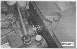
5.
Remove the three bolts (7) and the washers that hold
the governor in position. Carefully remove the governor
and the O-ring seal from the engine.
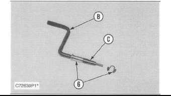
6.
Remove the governor connection tube (5) and the seal
from the cylinder head assembly. Remove the O-ring
seal from the cylinder head.
NOTE: The following steps a for the installation of the
governor.
7.
Check the condition of the O-ring seals used on the
governor, in the cylinder head, and on the connection
tube (5). If any of the seals are damaged, use new
parts for replacement. Install the O-ring seal in the
cylinder head. Install the governor connection tube with
the seal into the cylinder head.
8.
Put the governor in position on the engine. Install the
washers and three bolts (7) that hold it in position.
9.
Install the clevis pin (6) on the calibration Tool (B). Slide
the pilot pin insert Tool (B) in position. Install the pin
and the clip.
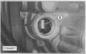
10.
If necessary, move the lever (8) in the governor housing
to align the components for installation of the clevis pin
(6). Pilot pin insert (A) will be used to align the mating
parts. Using Tool (B), install the pin (6). Install the clip.
11.
Check the fuel setting adjustment using the 128-8822
Tool Group. Refer to NEHS0610 Tool Operating
Manual for the procedure.
12.
Using Tool (A), slide the governor connection tube (5)
into the governor. Install the clip (4).
13.
Install fuel ratio control tube assembly (3), if equipped,
fuel tube assembly (2) and engine oil tube assembly (1).
14.
Install the governor control cable (linkage).
End By:
a.
Install fuel shutoff solenoid
8-15