
TM 5-3895-379-23-1
FIELD MAINTENANCE
TURBOCHARGER REPAIR
INITIAL SETUP:
Personnel Required
Tools and Special Tools
Construction Equipment Repairer 91L
Tool Kit, General Mechanic's: Automotive
(Volume 2, WP 0289, Table 1, Item 39)
Wrench, Torque, 20-100 ft-lb
References
(Volume 2, WP 0289, Table 1, Item 42)
TM 5-3895-379-10
TM 5-3895-379-23P, Figures 25 and 26
Materials/Parts
Sealing Compound, Loctite 271
Equipment Condition
(Volume 2, WP 0288, Table 1, Item 62)
Turbocharger removed. (WP 0121)
Tag, Marker
(Volume 2, WP 0288, Table 1, Item 70)
Gasket (Volume 2, WP 0290, Table 1, Item 53)
Qty: 1
DISASSEMBLY
NOTE
Tag and mark components for orientation before disassembly.
1.
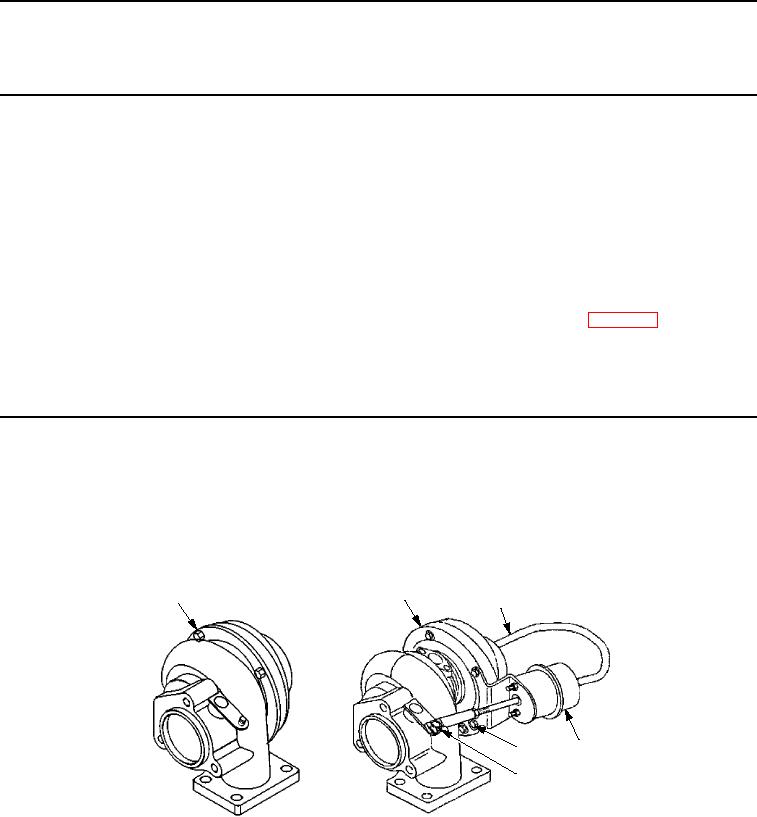
For CB534C Roller, disconnect hose (Figure 1, Item 2), remove screw (Figure 1, Item 5), two bolts
(Figure 1, Item 4), and actuator assembly (Figure 1, Item 3) from turbocharger group (Figure 1, Item 1).
1
1
2
3
4
5
CB534C ROLLER
CB534B ROLLER
M0501SWR
Figure 1.
Turbocharger Disassembly.
03/15/2011Rel(1.8)root(maintwp)wpno(M00060)