
TM 5-3895-379-23-1
0122
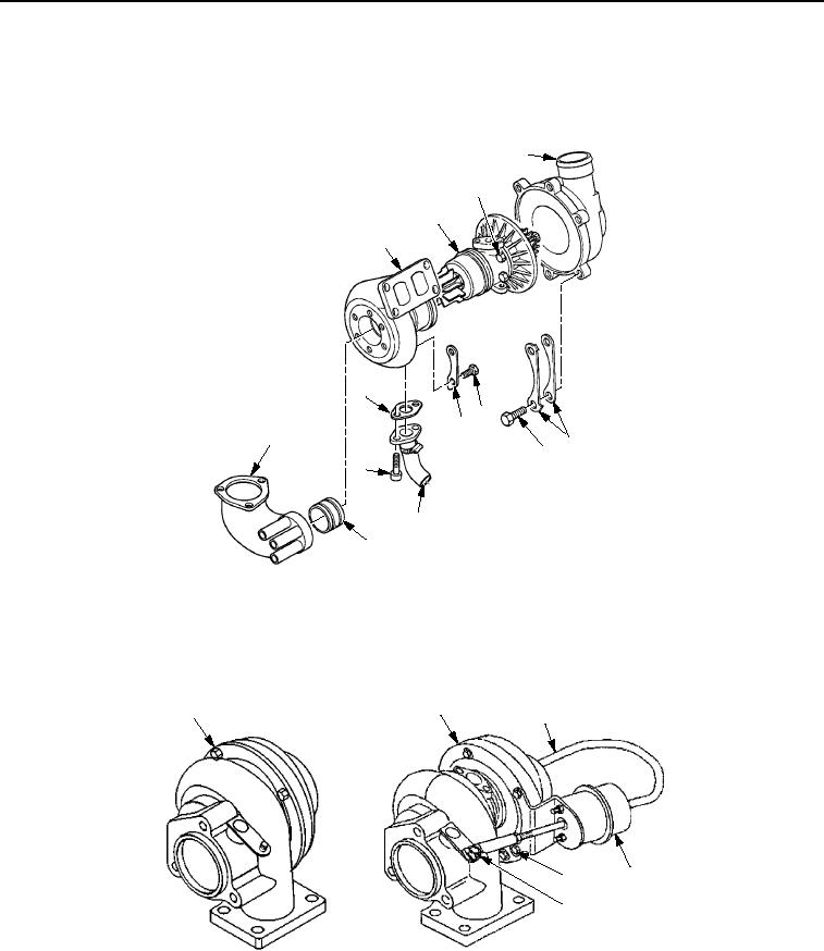
ASSEMBLY - Continued
6.
Install gasket (Figure 3, Item 12), hose assembly (Figure 3, Item 9), and two bolts (Figure 3, Item 13).
7.
Install outlet sleeve (Figure 3, Item 10) and exhaust elbow (Figure 3, Item 11) to housing (Figure 3, Item 1).
4
3
2
1
12
7
8
11
5
6
13
9
10
M1116SWR
Figure 3.
Turbocharger Assembly.
8.
For CB534C Roller, install screw (Figure 4, Item 5) to actuator assembly (Figure 4, Item 3). Install actuator
assembly (Figure 4, Item 3) to turbocharger group (Figure 4, Item 1). Connect hose (Figure 4, Item 2) and
install two bolts (Figure 4, Item 4) to turbocharger group (Figure 4, Item 1).
1
1
2
3
4
5
CB534C ROLLER
CB534B ROLLER
M0503SWR
Figure 4.
Turbocharger Assembly.
END OF TASK
03/15/2011Rel(1.8)root(maintwp)wpno(M00060)