
TM 5-3895-379-23-1
0111
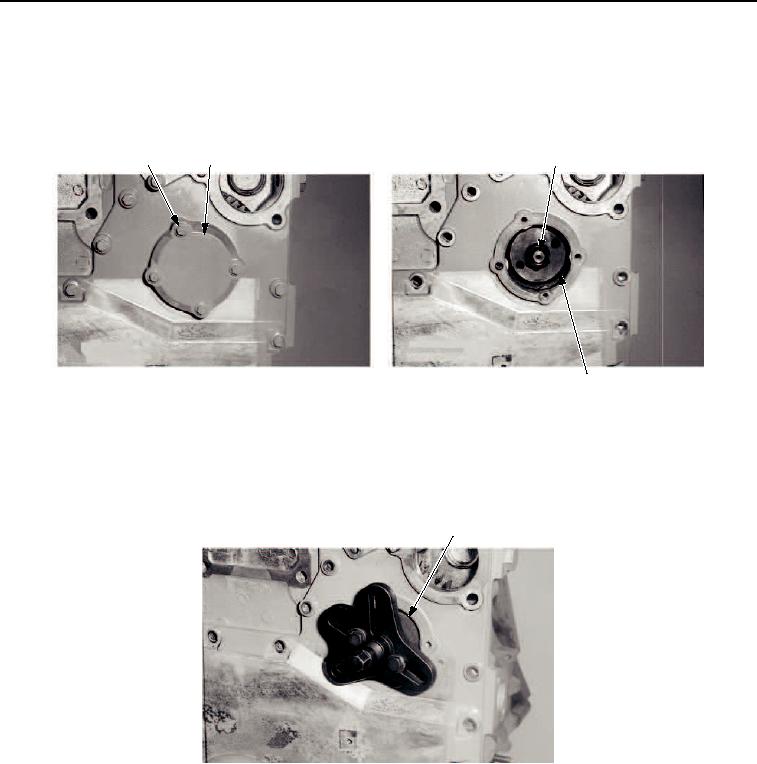
METHOD 2 (TIMING GEAR CASE COVER ON) REMOVAL
1.
Remove four bolts (Figure 3, Item 1) and cover (Figure 3, Item 2).
2.
Remove nut (Figure 3, Item 3) and washer (Figure 3, Item 4).
1
2
3, 4
M0140SWR
5
Figure 3. Fuel Injection Pump Gear Removal.
3.
Rotate crankshaft until keyway is at 1:00 o'clock.
4.
Install gear puller and disengage fuel injection pump gear (Figure 4, Item 1) from fuel injection pump
(Figure 4, Item 2).
1, 2
M1257SWR
Figure 4. Fuel Injection Pump Gear Removal.
END OF TASK
METHOD 2 (TIMING GEAR CASE COVER ON) INSTALLATION
1.
Install washer (Figure 5, Item 4) and nut (Figure 5, Item 3). Tighten nut to 58 lb-ft (78 Nm).
2.
Install four bolts (Figure 5, Item 1) and cover (Figure 5, Item 1).
03/15/2011Rel(1.8)root(maintwp)wpno(M00049)