
TM 5-3895-379-23-1
0110
INSTALLATION
CAUTION
Do not rotate injection nozzle after installation. The seal made by the anti-seize compound
could break. A broken seal may allow leakage past the seat of the fuel injection nozzle,
resulting in poor performance.
1.
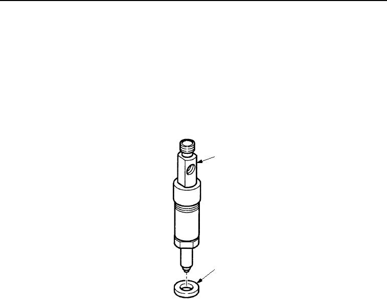
Clean threads on fuel injector (Figure 2, Item 1) and mating surface of cylinder head.
2.
Place a 0.08 in. (2.0 mm) bead of antiseize compound to the first two threads of injector (Figure 2, Item 1).
3.
Install washer (Figure 2, Item 2) on injector (Figure 2, Item 1).
1
2
M1117SWR
Figure 2.
Fuel Injector and Nozzle Installation.
03/15/2011Rel(1.8)root(maintwp)wpno(M00048)