
TM 5-3895-379-23-1
0110
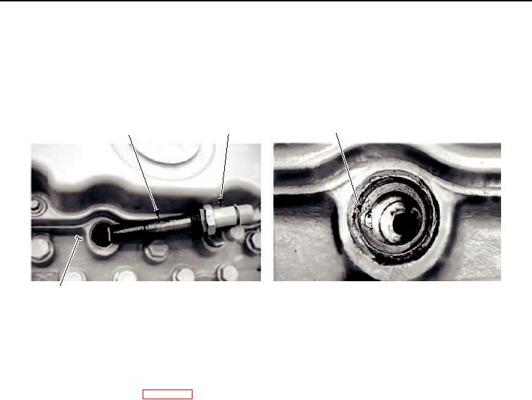
INSTALLATION - Continued
4.
Position injector (Figure 3, Item 2) by making sure detent ball (Figure 3, Item 1) is aligned with detent
(Figure 3, Item 3) in cylinder head (Figure 3, Item 4).
5.
Gradually and evenly tighten fuel injector (Figure 3, Item 2). Tighten to 264 lb-in. (30 Nm) and remove excess
antiseize compound.
3
1
2
M0138SWR
4
Figure 3. Fuel Injector and Nozzle Installation.
END OF TASK
FOLLOW-ON MAINTENANCE
1.
Install fuel injector lines. (WP 0115)
2.
Lower operator platform. (Volume 2, WP 0235)
3.
Start engine and check for leaks. (TM 5-3895-379-10)
END OF TASK
END OF WORK PACKAGE
03/15/2011Rel(1.8)root(maintwp)wpno(M00048)