
TM 5-3895-379-23-1
0105
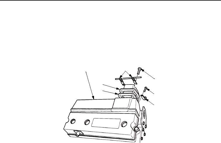
REMOVAL - Continued
3.
Loosen two hose clamps and slide hose at intake manifold flange (Figure 2, Item 7) toward the turbocharger.
4.
For CB534B Roller, remove screw (Figure 2, Item 4) and clip (Figure 2, Item 5) from intake manifold
(Figure 2, Item 1).
5.
Remove four bolts (Figure 2, Item 3).
6.
Remove clip (Figure 2, Item 2), clip (CB534B Roller), intake manifold flange (Figure 2, Item 7), and gasket
(Figure 2, Item 6) from intake manifold (Figure 2, Item 1). Discard gasket.
2
1
3
7
6
4
5
M0130SWR
Figure 2. Intake Manifold Removal.
03/15/2011Rel(1.8)root(maintwp)wpno(M00044)