
TM 5-3895-379-23-1
FIELD MAINTENANCE
OIL STRAINER AND SUCTION TUBE REPLACEMENT
INITIAL SETUP:
Personnel Required
Tools and Special Tools
Construction Equipment Repairer 91L
Tool Kit, General Mechanic's: Automotive
(Volume 2, WP 0289, Table 1, Item 39)
Gloves, Rubber
References
(Volume 2, WP 0289, Table 1, Item 12)
TM 5-3895-379-10
Goggles (Volume 2, WP 0289, Table 1, Item 13)
TM 5-3895-379-23P, Figure 14
Wrench, Torque, 0-300 in-lb
(Volume 2, WP 0289, Table 1, Item 41)
Equipment Condition
Oil pan removed. (WP 0093)
Materials/Parts
Cleaning Compound, Solvent
(Volume 2, WP 0288, Table 1, Item 13, 14,
15)
Gasket
(Volume 2, WP 0290, Table 1, Item 50)
Qty: 1
REMOVAL
1.
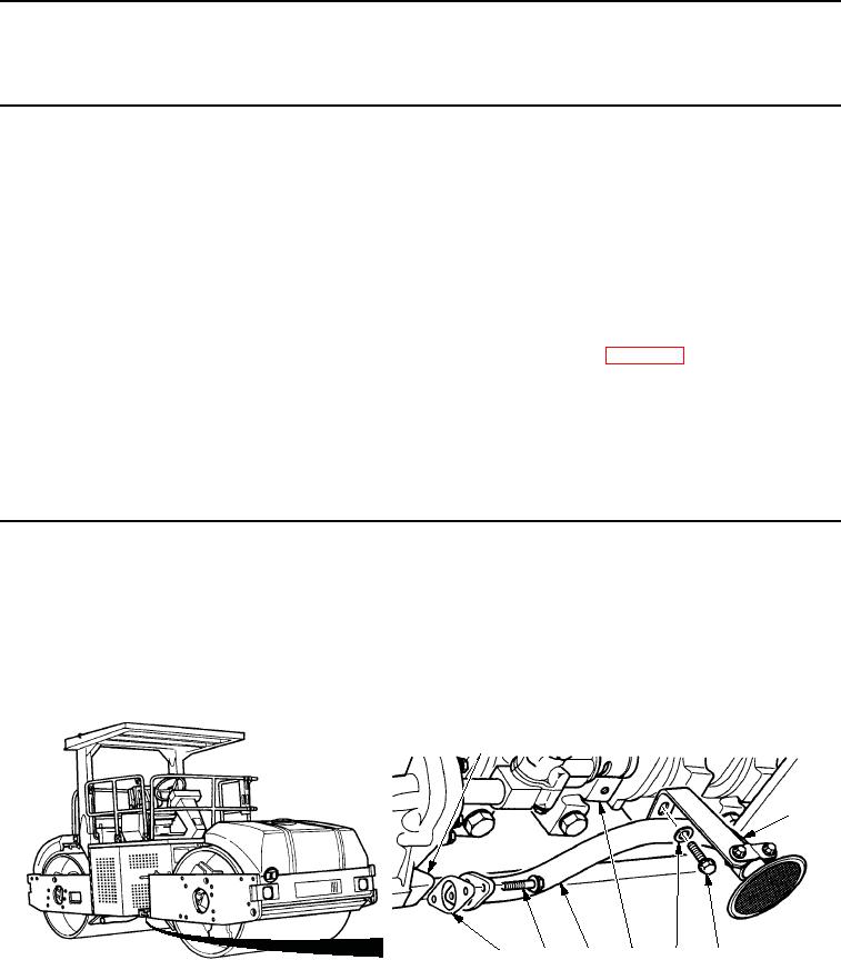
Remove two screws (Figure 1, Item 7) from strainer and suction tube assembly (Figure 1, Item 6) and oil pump
(Figure 1, Item 4).
2.
Remove screw (Figure 1, Item 3), washer (Figure 1, Item 4), strainer and suction tube assembly
(Figure 1, Item 6), gasket (Figure 1, Item 8), and bracket (Figure 1, Item 2) from bridge (Figure 1, Item 5).
Discard gasket.
1
2
8
7
6
5
4
3
M0126SWR
Figure 1.
Oil Strainer and Suction Tube Removal.
03/15/2011Rel(1.8)root(maintwp)wpno(M00043)