
TM 5-3895-379-23-1
0104
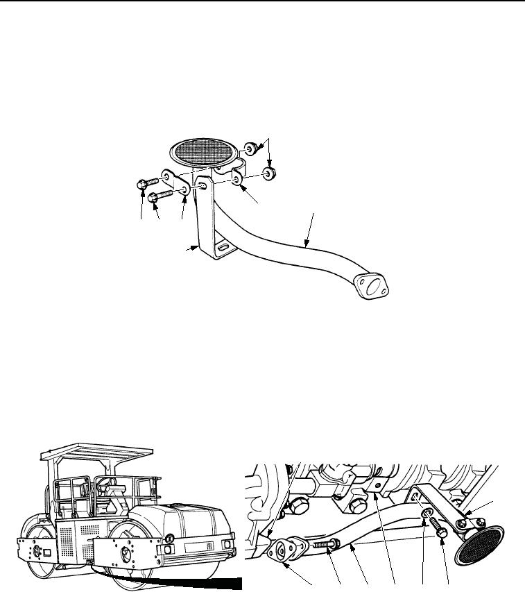
INSTALLATION
1.
Install retaining clip (Figure 3, Item 2) and mounting plate (Figure 3, Item 5) on strainer and suction tube
assembly (Figure 3, Item 3) with screw (Figure 3, Item 7) and nut (Figure 3, Item 1). Do not tighten nut.
2.
Install bracket (Figure 3, Item 4) on retaining clip (Figure 3, Item 2) and mounting plate (Figure 3, Item 5) with
screw (Figure 3, Item 6) and nut (Figure 3, Item 1). Do not tighten nut.
1
2
3
5
7
6
4
M1248SWR
Figure 3. Oil Strainer and Suction Tube Installation.
3.
Install new gasket (Figure 4, Item 8) and strainer and suction tube assembly (Figure 4, Item 6) on oil pump
(Figure 4, Item 4) with two screws (Figure 4, Item 7). Tighten screws to 192 lb-in. (22 Nm).
4.
Install bracket (Figure 4, Item 2) and strainer and suction tube assembly (Figure 4, Item 6) on bridge
(Figure 4, Item 5) with washer (Figure 4, Item 4) and screw (Figure 4, Item 3). Tighten screw to 192 lb-in.
(22 Nm).
5.
Tighten two nuts (Figure 3, Item 1).
1
2
8
7
6
5
4
3
M0128SWR
Figure 4.
Push Rod Cover Installation.
END OF TASK
03/15/2011Rel(1.8)root(maintwp)wpno(M00043)