
TM 5-3895-379-23-1
0102
REMOVAL
1.
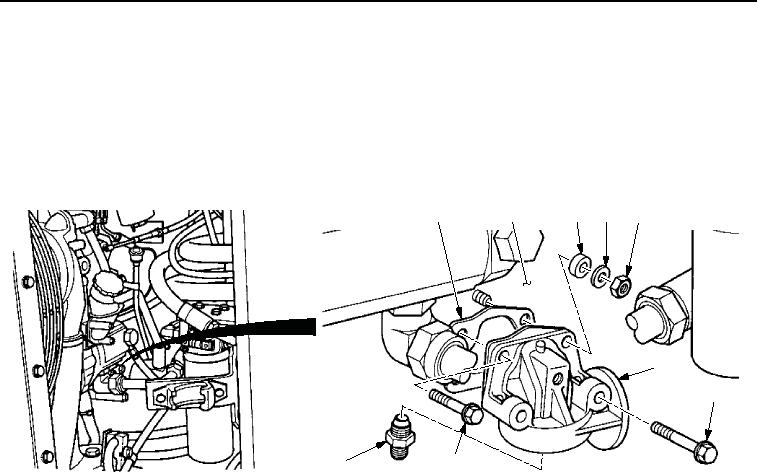
Remove two bolts (Figure 1, Item 7), nut (Figure 1, Item 5), washer (Figure 1, Item 4), spacer
(Figure 1, Item 3), oil filter head assembly (Figure 1, Item 6), and gasket (Figure 1, Item 1) from engine
(Figure 1, Item 2). Discard gasket.
2.
Remove bolt (Figure 1, Item 8) and connector (Figure 1, Item 9) from oil filter head assembly
(Figure 1, Item 6).
1
2
3
4
5
6
7
9
8
M0124SWR
Figure 1. Oil Filter Head Assembly Removal.
END OF TASK
03/15/2011Rel(1.8)root(maintwp)wpno(M00041)