
TM 5-3895-379-23-1
0083
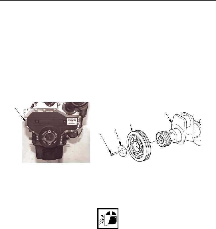
REMOVAL
NOTE
Some engines have water immersion seal on front cover. Front of seal has a flexible lip.
Plastic mandrel supplied with seal must be installed in seal when crankshaft pulley is
removed. This ensures lip maintains correct shape.
It may be necessary to keep crankshaft from rotating when removing bolts. Use
appropriate tool.
1.
Remove three bolts (Figure 1, Item 2) and counterbalance weight (Figure 1, Item 3) from end of crankshaft
(Figure 1, Item 5).
NOTE
It may be necessary to use a puller to remove crankshaft pulley.
2.
Remove crankshaft pulley (Figure 1, Item 4) from engine (Figure 1, Item 1).
1
5
4
3
2
M0070SWR
Figure 1. Crankshaft Pulley Removal.
END OF TASK
CLEANING
WARNING
Particles blown by compressed air are hazardous. DO NOT exceed 15 psi (103 kPa) nozzle
pressure when drying parts with compressed air. Use a maximum of 30 psi (207 kPa) when
cleaning components. DO NOT direct compressed air against human skin. Failure to follow
this warning may cause injury or death. Make sure air stream is directed away from user and
other personnel in the area. To prevent injury, user must wear protective goggles or face
shield.
Clean removed parts with detergent. Dry parts with compressed air.
END OF TASK
03/15/2011Rel(1.8)root(maintwp)wpno(M00022)