
SECTION 8
FINAL DRIVE AND TRANSFER CASE
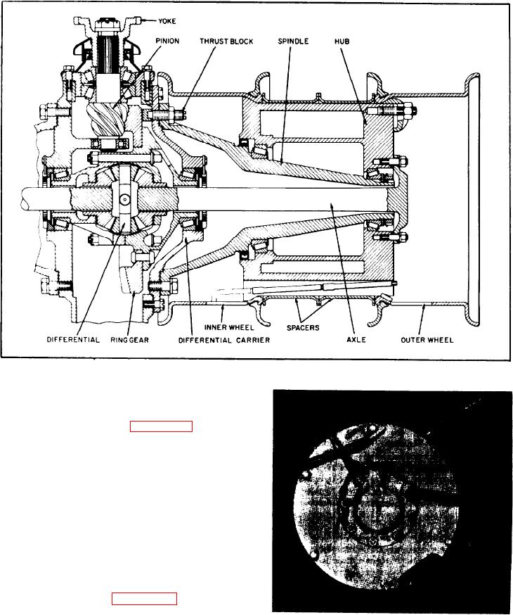
FIGURE 8-22.
.004 to .006 in. (.102 to .152 mm) when the
retainer nuts are tightened to 80 ft.-lbs. (11.06
kg-m).
8-21.
FINAL DRIVE (see figure 8-22).
8-22. GENERAL.
8-23. A single reduction, over-center pinion
type differential is used to drive the front drive
tires. Power is transmitted from the transfer
case to the final drive by a universal shaft.
6-24. The differential and ring gear assembly is
mounted on tapered roller bearings. The pinion
turns on two (2) tapered roller bearings in front
of the gear and a roller bearing behind the
gear.
8-25.
REMOVAL (see figure 8-22).
8-26. DIFFERENTIAL REMOVAL.
FIGURE 8-23.
a. Block up the left side of the front frame
b. Remove the lug nuts and sim retainer.
just enough that the drive tires are off the
Pull off the outer wheel, two (2) spacers and
ground.
inner wheel.
8-7.