
SECTION 8
FINAL DRIVE AND TRANSFER CASE
FIGURE 8-34.
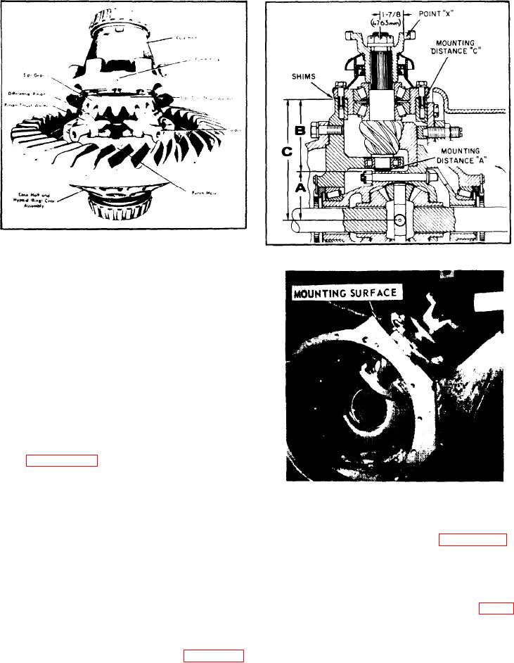
FIGURE 8-35.
suit individual working conditions.
Tonnage Required
Rivet Diameter
22
7/16 In. (11.11 mm)
30
1/2 In. (12.70 mm)
36
9/16 In. (14.29 mm)
45
5/8 In. (15.88 mm)
b. Lubricate differential case inner walls and
a l l component parts with axle lubricant.
Position thrust washer and side gear in case
half assembly. Place spider with pinions and
t h r u s t washers in position. Then install
remaining side gear and thrust washer.
c. Align mating marks and draw case halves
together with four (4) equally spaced capscrews
(see figure 8-34). Check assembly for free
rotation of differential gears and correct if
necessary. Install the remaining capscrews and
torque them to 185-205 ft.-lbs. (25.57-28.33
FIGURE 8-36.
kg-m). Install the lock wire.
in. (90.2 mm) from the end of the pinion to the
center line of the bevel ring gear and is stamp
d. Install the two (2) tapered roller bearings.
ed on the pinion shaft end (see figure 8-35).
Add or subtract, as indicated, the variation
8-37. INSTALLATION.
from the nominal value to obtain the actual
mounting distance "A".
NOTE: The pinion shaft assembly has to be
completely assembled and the pinion
b. Install pinion within .001 in. (.0254
nut torqued as described under RE-
mm) by installing shims where shown in figure
ASSEMBLY OF PINION SHAFT before
8-35. Coat capscrews with John Crane No. 2
measurements for shimming can be
sealer or equivalent and torque them to 55
taken.
ft.-lbs. (7.60 kg-m). Shim requirement may be
determined as follows:
8-38.
PINION INSTALLATION (see figure 8-35).
(1). Measure the distance from the pinion
a. The nominal mounting distance is 3.551
8-12.