
SECTION 7
TRANSMISSION
FIGURE 7-60.
FIGURE 7-62.
g. Pull the bearing off the output shaft.
the case (see figure 7-63).
h. Pull the sliding gear off the output shaft
I. Disassemble the countershaft only if
(see figure 7-69).
necessary and as follows:
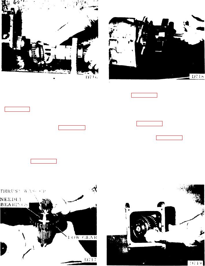
i. Set the forward end of the output shaft on
(1). Press the shaft out of the drive gear and
a clean surface. Lift the thrust washer off the
bearings (see figure 7-64).
output end of the shaft (see figure 7-61). Lift
the gear off the shaft. Be careful not to lose
(2). Remove the snap ring, retaining the
any bearings. Place them in a container.
intermediate gear (see figure 7-65). Press the
shaft out of the gear. Remove the second
NOTE: Count the bearings; there should be 39.
snap ring only if necessary.
j. Pull the rear countershaft bearing out of
7-69. CLEANING AND INSPECTION.
the housing (see figure 7-62).
a. The case may be steam cleaned. If
k. Lift the large gear end of the countershaft.
caustic solution is used, rinse all the caustic
Pull the shaft and gear assembly out the top of
from the case. Apply oil to all machined
FIGURE 7-61.
FIGURE 7-63.
7-18.