SECTION 7
TRANSMISSION
the case. Replace the gasket and the five
o-rings.
b. Install the four mounting capscrews and
lockwashers. Use Permatex 300 type gasket
s e a l (or equivalent) on the threads of the
capscrews.
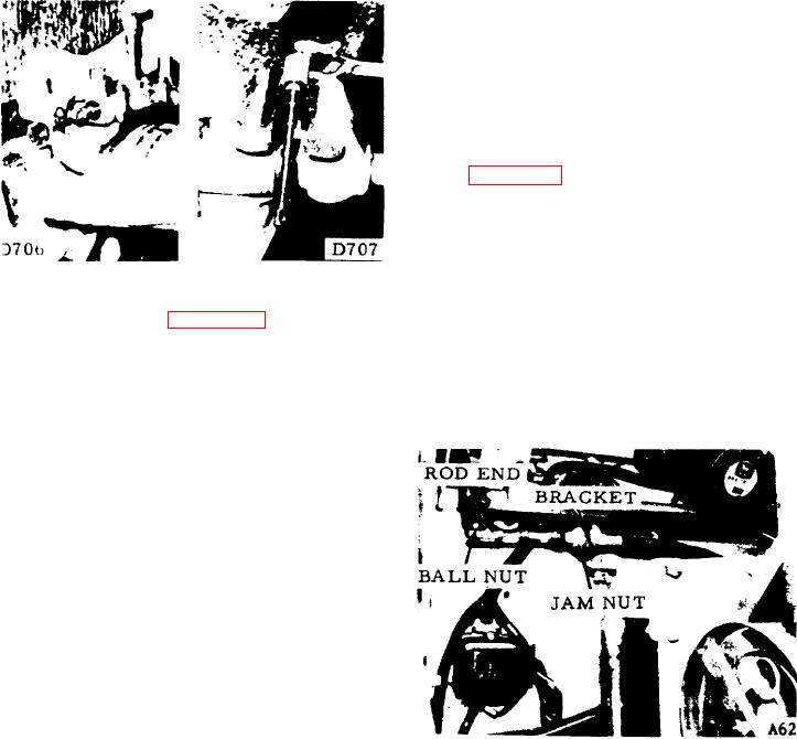
7-54. CONTROL CABLE ADJUSTMENT (see
a. Put the control valve spool into neutral.
b. Put the direction-control lever into neutral
- low idle position.
FIGURE 7-49.
FIGURE 7-50.
c. Tighten jam nuts on each side of cable
e. Clamp the barrel into a soft vise and
mounting bracket.
unscrew the cap (see figure 7-50).
d. Adjust rod ends at the control valve and
f . Extract the detent mechanism from the
under the dash board so that they will fit the
barrel, catching the spring and cups with a rag.
ball joints.
7-51. INSPECTION AND CLEANING.
e. Tighten jam nuts against rod ends.
a. Wash all parts with clean solvent.
b. Blow dry with air. Do not wipe parts dry
w i t h a rag to prevent lint from entering the
valve.
c. Inspect the spool for nicks, scratches and
burrs. Small scratches can be removed with
c r o c u s cloth. Large nicks and burrs require
replacement of the part.
d. Inspect o-rings and the seal for wear or
nicks and replace them if necessary.
7-52.
REASSEMBLY OF CONTROL VALVE.
a. install the o-ring, seal and cap at the
crank side of the case.
FIGURE 7-51.
b. Assemble the spring and detent cups in
7-55. PERFORMANCE CHECKS.
the spool.
7-56. HIGH IDLE.
c. Compress the spring with the cups and
slide assembly into the barrel.
7-57. Attach a tachometer to the engine with
d. install the cap.
the transmission in neutral. Rev up the engine
t o governed RPM with the transmission in
f o r w a r d . if governed RPM of 2800 is not
e. install the spool in the housing. Attach
the crank mechanism with the crosspin and
reached, c h e c k t h e c o n t r o l a n d g o v e r n o r
cotter pin.
linkage to make sure that the governor is held
wide open, or tune up the engine. Make the
7-53.
INSTALLATION OF CONTROL VALVE.
same check with the transmission in reverse.
a. Place the control valve assembly on top
7-58. CONVERTER STALL SPEED
of the case with the shift on the right side of
(1850 100 RPM).
7-14.

