
TM 5-3895-379-23
FLYWHEEL ASSEMBLY REPLACEMENT - CONTINUED
0168 00
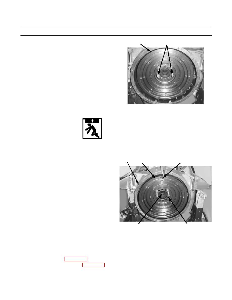
REMOVAL - CONTINUED
3
4
2.
Install two guide bolts (4) through flywheel assem-
bly (3) to crankshaft (5).
3.
Install link bracket (6) to flywheel assembly (3).
4.
Attach lifting device to link bracket (6).
5.
Remove remaining six bolts (1) and washers (2)
from flywheel assembly (3).
6.
With assistance, use lifting device to remove fly-
wheel assembly (3) from flywheel housing (7).
7.
Remove guide bolts (4) from crankshaft (5).
401-2236
INSTALLATION
WARNING
Use caution when handling heavy parts. Provide adequate support and use assistance during procedure.
Ensure that any lifting device used is in good condition and of suitable load capacity. Keep clear of
heavy parts supported only by lifting device. Failure to follow this warning may cause injury or death.
NOTE
7
3
6
If flywheel ring rear teeth are damaged,
replace flywheel assembly.
Weight of flywheel assembly is 120 lb (54
kg).
1.
Install two guide bolts (4) to crankshaft (5). Install
link bracket (6) to flywheel assembly (3).
2.
Install link bracket (6) to flywheel assembly (3).
3.
Attach lifting device to link bracket (6) and flywheel
assembly (3).
4.
With assistance, lift flywheel assembly (3) into fly-
wheel housing (7).
5.
Install six washers (2) and bolts (1) into flywheel
401-2237
1,2
5
assembly (3) and crankshaft (8). Tighten bolts to 77
lb-ft (104 Nm).
6.
Remove lifting device and link bracket (6) from flywheel assembly (3).
7.
Remove guide bolts (4) from flywheel assembly (3).
8.
Install remaining two washers (2) and bolts (1) into flywheel (3) and crankshaft (8). Tighten bolts to 77 lb-ft (104
Nm).
9.
Install starter assembly (WP 0066 00).
10.
Install vibratory and propel pumps (WP 0187 00).
END OF WORK PACKAGE
0168 00-2
