
TM 5-3895-379-23-2
0254
INSTALLATION
WARNING
Use caution when handling heavy parts. Provide adequate support and use assistance during
procedure. Failure to follow this warning may cause injury.
NOTE
The weight of the vibration cooling/control valve is 62 lb (28 kg).
Prior to installation, lubricate O-rings with a light coat of lubricating oil.
1.
Install four new O-rings (Figure 2, Item 8) on spacer (Figure 2, Item 7) and vibratory cooling/control valve
(Figure 2, Item 6).
2.
With assistance, position vibratory cooling/control valve and spacer (Figure 2, Item 7) to vibratory pump
(Figure 2, Item 9) and install six bolts (Figure 2, Item 5).
NOTE
Remove caps and plugs before connecting hose assemblies.
3.
Connect seven hose assemblies (Figure 2, Item 4) to vibratory cooling/control valve (Figure 2, Item 6).
4.
Position electrical harness to bracket (Figure 2, Item 2) and fasten electrical tiedown straps (Figure 2, Item 1)
to secure electrical harness.
5.
Connect two electrical connectors (Figure 2, Item 3) to vibratory cooling/control valve (Figure 2, Item 6).
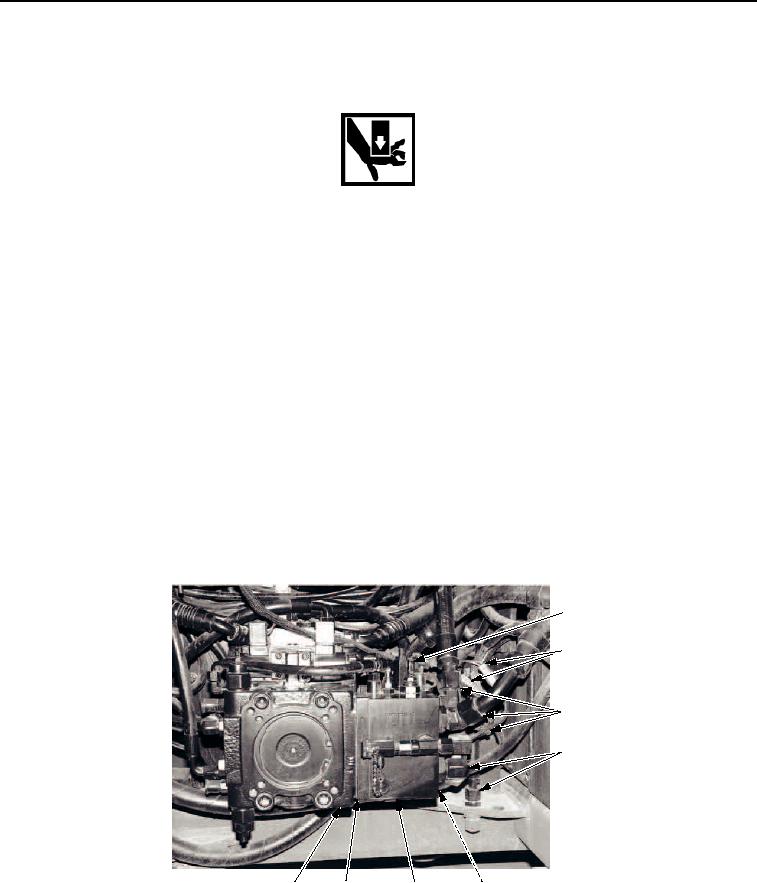
1, 2
3
4
4
M1284SWR
9
7, 8
6
5
Figure 2. Vibratory Cooling/Control Valve Installation.
END OF TASK
03/15/2011Rel(1.8)root(maintwp)wpno(M00192)