
TM 5-3895-379-23-2
0253
DISASSEMBLY - Continued
1, 2, 3
4, 5, 6
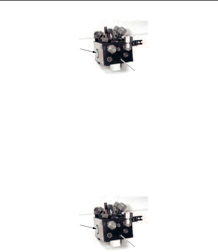
M0821SWR
Figure 2. Vibratory Cooling/Control Valve Removal.
END OF TASK
CLEANING AND INSPECTION
1.
Before the vibratory cooling/control valve is assembled, make sure all valve parts are clean, dry, and free of
all dirt and foreign material.
2.
Inspect all parts for damage or wear and replace worn or damaged parts if found.
3.
Lubricate all back-up rings and O-rings with clean lubricating oil prior to assembly.
END OF TASK
ASSEMBLY
1.
Install two new O-rings (Figure 3, Item 6), one new back-up ring (Figure 3, Item 5), and check valve
(Figure 3, Item 4) in valve block (Figure 4, Item 11). Tighten relief valve to 180 lb-in. (20 Nm).
2.
Install three new O-rings (Figure 3, Item 3), two new back-up rings (Figure 3, Item 2), and shuttle valve
(Figure 3, Item 1) to valve block (Figure 4, Item 11). Tighten shuttle valve to 65 lb-ft (88 Nm).
1, 2, 3
4, 5, 6
M1215SWR
Figure 3. Vibratory Cooling/Control Valve Assembly.
03/15/2011Rel(1.8)root(maintwp)wpno(M00191)