
TM 5-3895-379-23-2
0255
INSTALLATION - Continued
5.
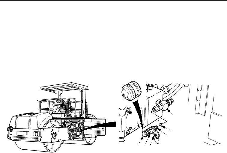
Install new O-ring (Figure 4, Item 2) on hydraulic oil sampling valve (Figure 4, Item 5).
NOTE
When installing hydraulic oil sampling valve, position drain down for ease in sample collection.
6.
Apply sealing compound to threads of hydraulic oil sampling valve (Figure 4, Item 5) and position on tee
(Figure 4, Item 1). Tighten locking nut (Figure 4, Item 3).
7.
Install hydraulic oil sampling valve drain cap (Figure 4, Item 4) on hydraulic oil sampling valve
(Figure 4, Item 5).
1
2
3
6 5 4
M1132SWR
Figure 4. Hydraulic Oil Sampling Valve Installation.
END OF TASK
FOLLOW-ON MAINTENANCE
1.
Close left-side door assembly. (TM 5-3895-379-10)
2.
Fill hydraulic tank. (Volume 1, WP 0124)
3.
Start engine and check for leaks. (TM 5-3895-379-10)
4.
Remove chocks. (TM 5-3895-379-10)
END OF TASK
END OF WORK PACKAGE
03/15/2011Rel(1.8)root(maintwp)wpno(M00193)