
TM 5-3895-379-23-2
0252
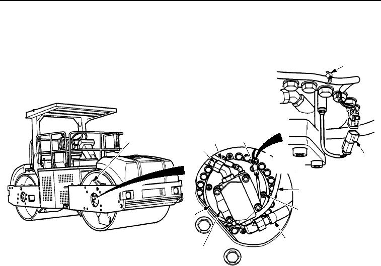
INSTALLATION
1.
With assistance, position vibratory motor (Figure 3, Item 8) to drum (Figure 3, Item 1) and install to driveshaft.
5
4
1
3
2
4
3
6, 7
9
2
8
M1259SWR
Figure 3.
Vibratory Motor Installation.
03/15/2011Rel(1.8)root(maintwp)wpno(M00190)