
TM 5-3895-379-23-2
0252
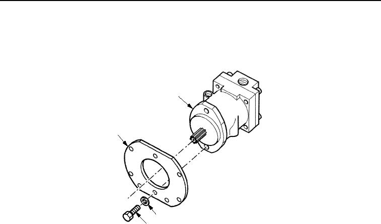
INSTALLATION - Continued
2.
Install four washers (Figure 4, Item 3) and bolts (Figure 4, Item 4) through plate (Figure 4, Item 1) to fasten
vibration motor (Figure 4, Item 2).
2
1
3
4
M1260SWR
Figure 4.
Vibratory Motor Installation.
3.
Install four washers (Figure 3, Item 7) and nuts (Figure 3, Item 6) on plate (Figure 3, Item 9).
NOTE
Remove all caps and plugs from hoses and openings prior to assembly.
4.
Connect two hose assemblies (Figure 3, Item 3) and two hose assemblies (Figure 3, Item 2) to vibratory motor
(Figure 3, Item 8).
5.
Connect electrical connector (Figure 3, Item 4) and install new electrical tiedown strap (Figure 3, Item 5).
END OF TASK
FOLLOW-ON MAINTENANCE
1.
Fill hydraulic tank. (Volume 1, WP 0124)
2.
Close left-side door assembly. (TM 5-3895-379-10)
3.
Battery switch to ON position. (TM 5-3895-379-10)
4.
Operate roller and check for proper operation and leaks. (TM 5-3895-379-10)
END OF TASK
END OF WORK PACKAGE
0252-5/6 blank
03/15/2011Rel(1.8)root(maintwp)wpno(M00190)