
TM 5-3895-379-23-2
0253
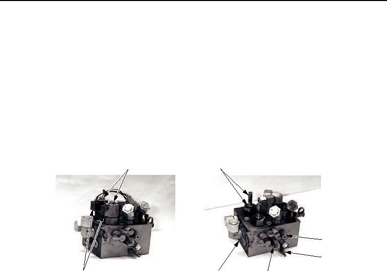
DISASSEMBLY
1.
Remove two nuts (Figure 1, Item 1) and coil assemblies (Figure 1, Item 12) from valve solenoids
(Figure 1, Item 2).
2.
Remove two valve solenoids (Figure 1, Item 2) and O-rings (Figure 1, Item 3) from valve block
(Figure 1, Item 11).
3.
Remove charge relief valve (Figure 1, Item 4) and O-ring (Figure 1, Item 5) from valve block
(Figure 1, Item 11). Discard O-ring.
4.
Remove spike relief valve (Figure 1, Item 8), two back-up rings (Figure 1, Item 9), and O-rings
(Figure 1, Item 10) from valve block (Figure 1, Item 11). Discard back-up rings and O-rings.
5.
Remove Pressure Override Relief (POR) valve (Figure 1, Item 6) and O-ring (Figure 1, Item 7) from valve block
(Figure 1, Item 11). Discard O-ring.
1
2, 3
4, 5
6, 7
12
11
8, 9, 10
M0820SWR
Figure 1.
Vibratory Cooling/Control Valve Removal.
6.
Remove shuttle valve (Figure 2, Item 1), two back-up rings (Figure 2, Item 2), and three O-rings
(Figure 2, Item 3) from valve block (Figure 1, Item 11). Discard back-up rings and O-rings.
7.
Remove check valve (Figure 2, Item 4), back-up ring (Figure 2, Item 5), and two O-rings (Figure 2, Item 6) from
valve block (Figure 1, Item 11). Discard back-up ring and O-rings.
03/15/2011Rel(1.8)root(maintwp)wpno(M00191)