
TM 5-3895-379-23-2
0251
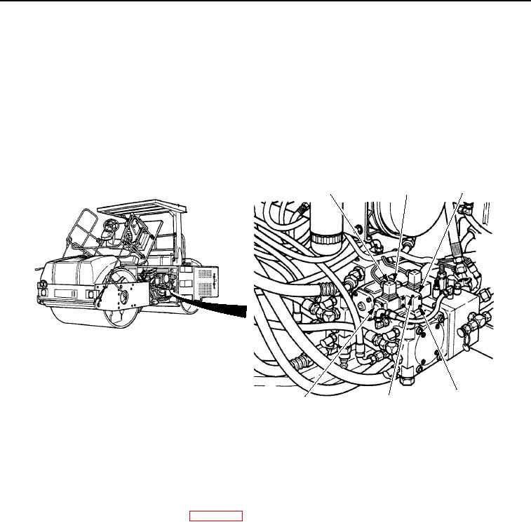
INSTALLATION
1.
Install two solenoids (Figure 2, Item 6) to vibratory control valve body (Figure 2, Item 5).
2.
Install vibratory control valve body (Figure 2, Item 3) to roller.
3.
Install four bolts (Figure 2, Item 4) and one bolt (Figure 2, Item 5) to vibratory control valve body
(Figure 2, Item 3).
4.
Install two electrical connectors (Figure 2, Item 2) to two solenoids (Figure 2, Item 6).
5.
Install two screws (Figure 2, Item 1) that fasten two electrical connectors (Figure 2, Item 2) to two solenoids
(Figure 2, Item 6).
1
2
3
4
5
6
M0817SWR
Figure 2.
Vibratory Control Solenoid Installation.
END OF TASK
FOLLOW-ON MAINTENANCE
1.
Lower operator platform assembly. (WP 0235)
2.
Close left-side door assembly. (TM 5-3895-379-10)
END OF TASK
END OF WORK PACKAGE
0251-3/4 blank
03/15/2011Rel(1.8)root(maintwp)wpno(M00189)