TM 5-3895-379-23-1
0202
SEPARATE - Continued
3
2
1
M0352SWR
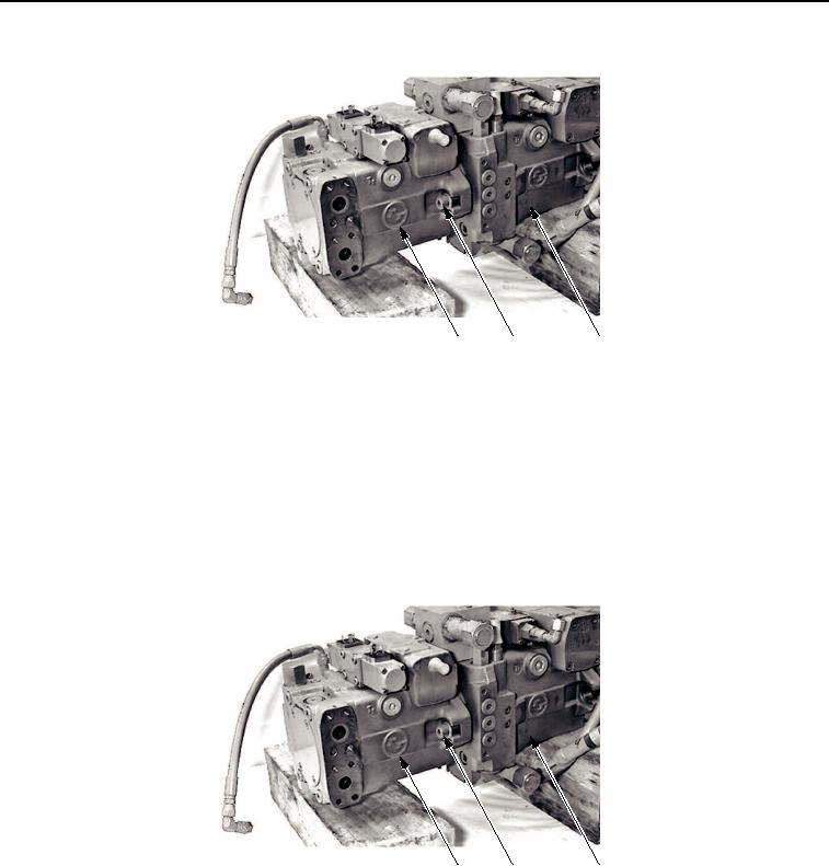
Figure 2.
Vibratory and Propel Pumps Separate.
END OF TASK
CONNECT
1.
Connect propel pump (Figure 3, Item 1) to vibratory pump (Figure 4, Item 2) with two bolts (Figure 3, Item 2).
2.
Install four new O-rings (Figure 3, Item 3) on spacer (Figure 4, Item 5) and vibratory control valve
(Figure 4, Item 4).
3
2
1
M1226SWR
Figure 3.
Vibratory and Propel Pumps Connect.
03/15/2011Rel(1.8)root(maintwp)wpno(M00140)

