
TM 5-3895-379-23-1
0143
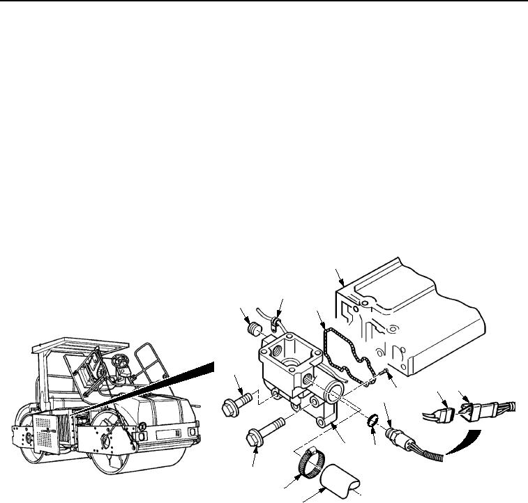
INSTALLATION
1.
Install pipe plug (Figure 2, Item 1) in thermostat housing assembly (Figure 2, Item 10).
2.
Position new O-ring (Figure 2, Item 3) on thermostat housing assembly (Figure 2, Item 10).
3.
Position hose (Figure 2, Item 11) onto thermostat housing assembly (Figure 2, Item 10).
4.
Install three bolts (Figure 2, Item 14) and two bolts (Figure 2, Item 13) in thermostat housing assembly
(Figure 2, Item 10). Tighten bolts to 33-47 lb-ft (45-64 Nm).
5.
Install clamp (Figure 2, Item 12) on hose (Figure 2, Item 11) and thermostat housing assembly
(Figure 2, Item 10). Tighten clamp until secure.
6.
Install clip (Figure 2, Item 2) on thermostat housing assembly (Figure 2, Item 10) with screw
(Figure 2, Item 7).
7.
Install O-ring (Figure 2, Item 9) and temperature sensor (Figure 2, Item 8) in thermostat housing assembly
(Figure 2, Item 10).
8.
Connect temperature sensor connector (Figure 2, Item 5) to connector (Figure 2, Item 6).
4
2
1
3
14
6
5
7
8
9
10
13
12
11
M1108SWR
Figure 2. Thermostat Housing Installation.
END OF TASK
03/15/2011Rel(1.8)root(maintwp)wpno(M00081)