
TM 5-3895-379-23-1
FIELD MAINTENANCE
EXHAUST MANIFOLD REPLACEMENT (CB534C)
INITIAL SETUP:
References
Tools and Special Tools
TM 5-3895-379-10
Tool Kit, General Mechanic's: Automotive
TM 5-3895-379-23P, Figure 16
(Volume 2, WP 0289, Table 1, Item 39)
Wrench, Torque, 20-100 ft-lb
(Volume 2, WP 0289, Table 1, Item 42)
Equipment Condition
Turbocharger removed. (WP 0121)
Intake manifold removed. (WP 0105)
Materials/Parts
Antiseize Compound
(Volume 2, WP 0288, Table 1, Item 8)
Gasket (Volume 2, WP 0290, Table 1, Item 20)
Qty: 1
Personnel Required
Construction Equipment Repairer 91L
REMOVAL
NOTE
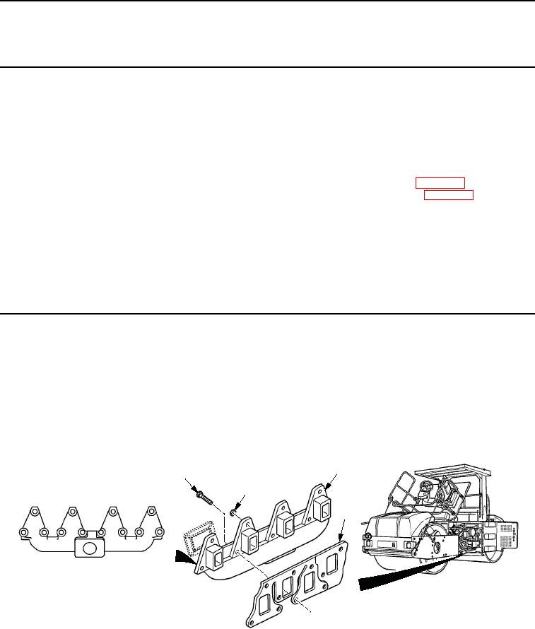
Note number and location of bolts (Figure 1, Item 1) or nuts (Figure 1, Item 2) to insure proper
installation.
1.
Remove bolts (Figure 1, Item 1) and nuts (Figure 1, Item 2) in reverse order (see Tightening Sequence).
2.
Remove exhaust manifold (Figure 1, Item 3) and gasket (Figure 1, Item 4) from engine. Discard gasket.
3
1
2
5
2
11
8
4
4
7
3
12
10
9
6
1
TIGHTENING SEQUENCE
M0133SWR
Figure 1.
Exhaust Manifold Removal.
END OF TASK
03/15/2011Rel(1.8)root(maintwp)wpno(M00046)