
TM 5-3895-379-23-1
FIELD MAINTENANCE
FUEL INJECTOR AND NOZZLE REPLACEMENT (CB534B)
INITIAL SETUP:
Personnel Required
Tools and Special Tools
Construction Equipment Repairer 91L
Tool Kit, General Mechanic's: Automotive
(Volume 2, WP 0289, Table 1, Item 39)
Wrench, Torque, 0-300 in-lb
References
(Volume 2, WP 0289, Table 1, Item 41)
TM 5-3895-379-10
TM 5-3895-379-23P, Figure 17
Materials/Parts
Cap Set, Protective, Dust and Moisture Seal
Equipment Condition
(Volume 2, WP 0288, Table 1, Item 12)
Operator platform assembly raised.
Rag, Wiping
(Volume 2, WP 0235)
(Volume 2, WP 0288, Table 1, Item 60)
Fuel injector lines removed. (WP 0114)
Gasket (Volume 2, WP 0290, Table 1, Item 46)
Qty: 1
REMOVAL
CAUTION
Cap and plug all openings to prevent any contaminants from entering the system.
NOTE
All fuel injector nozzles are replaced the same way. One fuel injector nozzle is shown.
1.
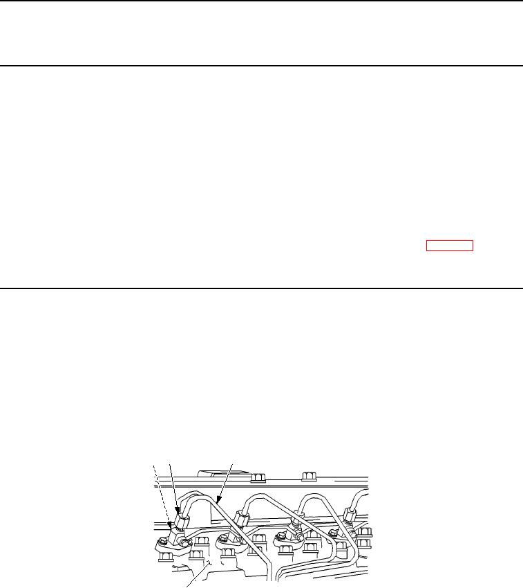
Remove two capscrews (Figure 2, Item 1) and clamp (Figure 2, Item 2) from cylinder head (Figure 1, Item 4).
2.
Remove fuel injector (Figure 2, Item 3) and washer (Figure 2, Item 7) from cylinder head (Figure 1, Item 4).
3
2
1
4
M0135SWR
Figure 1. Fuel Injector and Nozzle Removal.
03/15/2011Rel(1.8)root(maintwp)wpno(M00047)