
SECTION 10
BRAKES
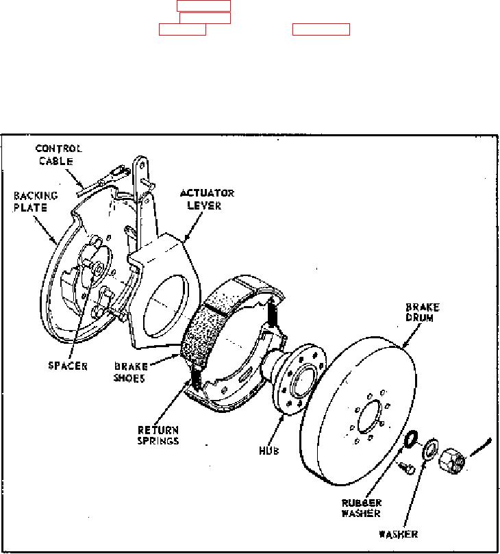
the left-hand side of the final drive housing. It is
SECTION 10
operated by a handlever mounted to the gooseneck. A
flexible teflon coated steel cable connects the braking
10-1. GENERAL.
mechanism to the handlever. When the handlever is
10-2. This section contains a description of the parking
pulled, the cable retracts, operating an actuator lever
brake system and repair instruction for the brake drum
which forces the brake shoe-type lining against the
assembly. Repair instructions include removal,
Inside of the brake drum. The brake drum is splined to
inspection, and installation of the park brake assembly.
the final drive shaft.
10-3. Design specifications are given in Section 2.
10-6. REMOVAL AND DISASSEMBLY (see
Maintenance requirements are discussed in Section 4.
Troubleshooting instructions are given in Section 5.
10-7. Block guide roll and drive drums prior to removal
10-4. DESCRIPTION.
of the brake drum assembly to prevent movement of the
unit. Set the parking brake handlever to the brake
10-5. The parking brake is a mechanically operated
applied position. Remove parking brake access cover
friction brake mechanism that prevents the final drive
located on the rear of the left-hand frame channel.
from rotating. The braking mechanism is mounted on
FIGURE 10-1.
10-1.