
SECTION 9
STEERING
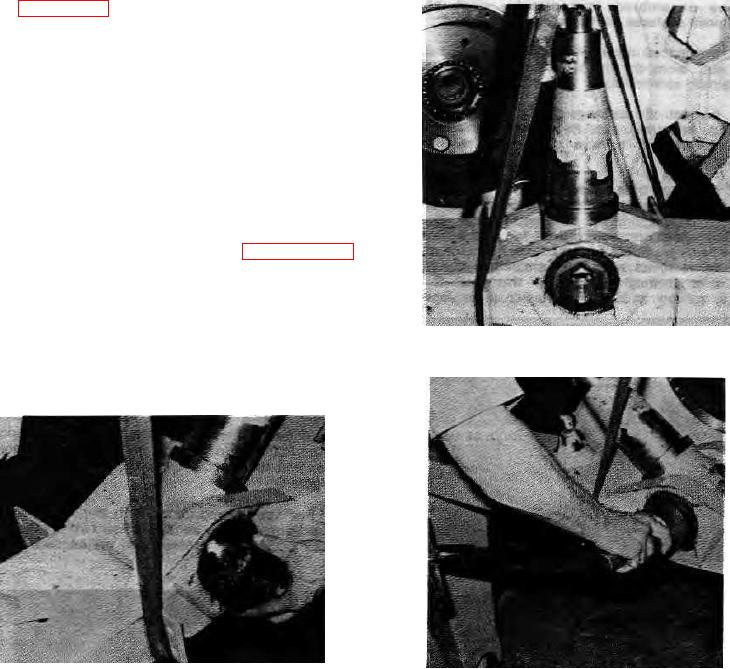
pin (see figure 9-126). Tighten slotted nuts equally so that
king pin remains centered on yoke. Torque one slotted nut
to 200 ft.-lbs. (27.7 kg-m) lubed then back off to loose and
retorque to 75 ft.-lbs. (10.4 kg-m). Check torque on
opposite slotted nut. It should be 75 ft.-lbs. (10.4 kg-m).
NOTE:
Check that running clearance exists on both
sides of king pin. Adjust if necessary by
repeating step h.
i. Install cotter keys into slotted nuts on both ends of
the oscillation pin. Fill dust caps half full with Hyster
approved multipurpose grease and install.
j.
Install guide roll assembly (refer to paragraph 9-96).
k. Place unit on ground so that entire weight of
gooseneck rests on king pin. Torque slotted nut to 200 ft.-
lbs. (27.7 kg-m) lubed. Back off to loose and retorque to
75 ft.-lbs. (10.4 kg-m).
FIGURE 9-126A..
I. Install cotter key and fill dust cap half full with
Hyster approved multipurpose grease and install.
FIGURE 9-125.
FIGURE 9-126B.
9-39.