SECTION 10
BRAKES
d.
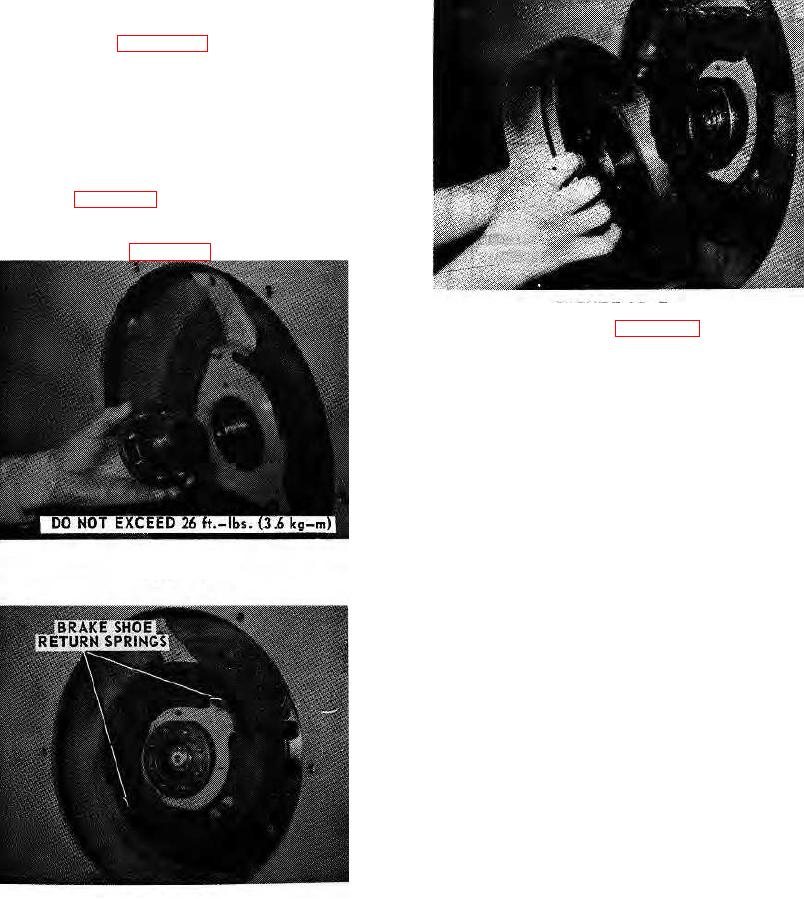
Next install brake hub, rubber seal, washer and
slotted nut (see figure 10-5).Tighten slotted nut to
remove end play. Back off one (1) flat (.012 in. - .305
mm loose). DO NOT EXCEED 26 FT.-LBS. TORQUE.
Secure with cotter pin
e. Install brake shoes and return springs in position
shown (see figure 10-6).
f. Install brake drum and torque capscrews to 49 ft.-
lbs. (6.8 kg-m) (see figure 10-7).
FIGURE 10-7.
10-10. ADJUSTMENT (see figure 10-8).
10-11. The parking brake handlever should be adjusted
sufficiently to require at least 80 pounds (36.3 kg) to pull
it into the applied position. Turn the adjusting knob on
the handlever clockwise (lever in brake-off position) to
increase force required to apply the brake.
10-12. Whenever the brake lining wears to the point
where the brake cannot be adjusted with the handlever
adjusting knob or when new lining is installed because of
wear, another adjustment must be made. This
adjustment is made in the linkage on the actuator lever
end of the brake cable.
FIGURE 10-5.
a. Disconnect the brake cable from the actuator lever
and loosen the cable end jam nut on the cable.
b. Push the actuator lever arm until the shoes contact
the brake drum. Adjust cable end until it aligns with the
actuator lever arm in the shoe contact position.
c. Connect the cable to the actuator lever and adjust
the handlever to obtain maximum braking power.
10-13. BRAKE LINING BREAK-IN PROCEDURE.
CAUTION: Break-in is essential to ensure adequate
braking of the unit.
a. Jack the drive roll off the ground.
b. Warm up unit (Hydraulic oil temperature 100F).
FIGURE 10-6.
10-3.

