
SECTION 9
STEERING
9-1. GENERAL.
position of the steering cylinders.
9-2. This section contains a description of the
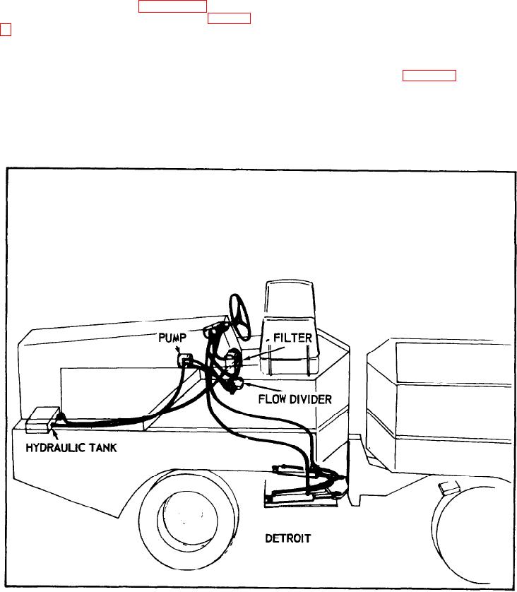
9-4. Components of the steering arrangement
are:
steering system operation and overhaul instruc-
tions for the major components. Overhaul
(1). an engine mounted hydraulic power
instructions include removal, disassembly,
pump
inspection and installation procedures. Specifi-
(2). the dashboard mounted basic power
cations are given in Section 2 and a
steering control unit
troubleshooting guide is presented in Section
(3). two double acting hydraulic steering
cylinders
(4). steering wheel
(5). hydraulic fluid reservoir
(6). hydraulic lines and fittings
(7). hydraulic filter (see figure 9-1).
9-5. OPERATION.
9-6. POWER OPERATION.
9-3. The steering system has a neutral feel to
the operator by providing a direct relation
9-7. With no turning force yet applied, the
between the steering wheel position and the
power pump (engine mounted) circulates oil
FIGURE 9-1.
9-1.