
SECTION 7
TRANSMISSION
d . Lower the reverse clutch hub on the
o u t p u t shaft, thrust face down (see figure
FIGURE 7-28.
FIGURE 7-27.
Make sure that the snap ring is securely seated
in its groove (see figure 7-23).
FIGURE 7-31.
FIGURE 7-32.
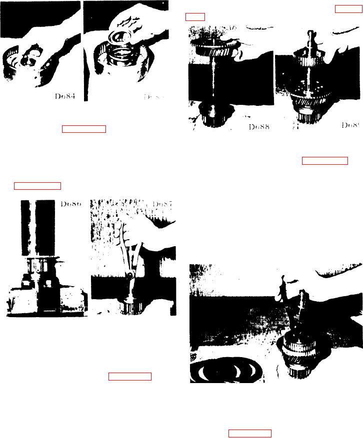
7-37. REASSEMBLY OF REVERSE CLUTCH-
SHAFT AND PACK.
e. Install the snap ring (see figure 7-33) on
the output shaft to retain the rear clutch hub,
a. Press the output bearing on the output
making sure that the ring is securely seated in
shaft assembly and secure it with a lock ring
i t s groove. Check the output gear for free
(see figures 7-29 and 7-30).
motion.
f. Prelubricate and install the two seal rings
in the two grooves on the output shaft.
CAUTION: Do not place a friction plate against
the clutch piston. Use a steel
separator plate.
FIGURE 7-30.
FIGURE 7-29.
b. Install a thrust bearing. Slide an oiled
caged needle bearing over the shaft.
c. Install the output gear assembly, followed
by another thrust bearing (see figure 7-31).
FIGURE 7-33.
NOTE: The steel separator plates are slightly
conical (dished). Install all plates the
same way - with the "dished" side up
(see figure 7-34).
CAUTION: Center the seal rings in the shaft
grooves so that they are not
damaged when the clutch cylinder
assembly is lowered into place.
7-9.