TM 5-3895-383-24
47.
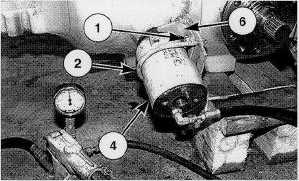
Position bracket (6) and brake actuator (4). Install two
nuts and bolts (1) that hold bracket (6) in place. Install
clamp (2) and the two nuts.
48.
Connect a source of hydraulic pressure to the inlet port
of brake actuator (4) as shown.
49.
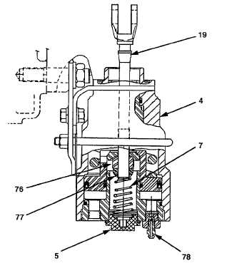
Install retainer (76) on brake control rod (19) and tighten
snugly.
50.
Apply 1100 to 1380 kPa (160 to 200 psi) of hydraulic
pressure to the brake actuator.
51.
Use bleed screw to remove any air that may be trapped
in the brake actuator. Maintain the 1100 to 1380 kPa
(160 to 200 psi) of hydraulic pressure.
52.
Tighten retainer (76) to a torque of 5.6 Nm (50 lb-in).
Then back off (turn counterclockwise) retainer (76) 1-1/3
turns (8 flats).
53.
Release the hydraulic pressure to the brake actuator,
and install the fitting.
54.
Install lock nut (77) on brake control rod (19) until It
contacts retainer (76). Do not allow retainer (76) to turn
in relation to brake control rod (19).
55.
Install spring (7), the gasket and plug (5) in the brake
actuator. Tighten the plug to a torque of 24 to 27 Nm
(18 to 20 lb-ft).
56.
Repeat Steps 47 thru 55 for the remaining brake
actuator.
57.
After both brake actuators have been adjusted, apply
1100 to 1380 kPa (160 to 200 psi) of hydraulic pressure
to each of the brake actuators. Make sure that both
sides of the axle rotate freely.
58.
Connect hose assembly (3) between the two brake
actuators.
End By:
a.
install axle
NOTE:
After the axle has been installed, fill the axle
housings with oil to the correct levels. See the
Operation & Maintenance Manual for the correct
procedure.
14-83