TM 5-3895-383-24
3.
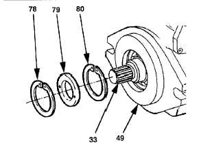
Install shaft (33) and bearing (81) in pump housing (49).
4.
Install retaining ring (80), seal (79) and retaining ring
(78) in the pump housing.
NOTE:
Steps 5a through 5e are provided for reference
only.
5.
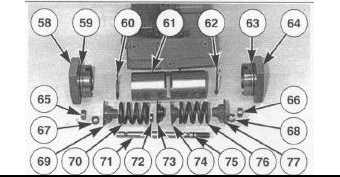
Assemble servo piston assembly (56) as follows:
a.
Install rod (71) in piston (61).
b.
Install collar (74) and spring (76) on rod (71).
Carefully compress spring (76), and install collar (77),
keepers (68), retainer (66) and retaining ring (62).
Slowly release the spring tension.
c.
Install collar (73), spacer (72) and spring (70) on rod
(71). Carefully compress spring (70), and install collar
(69), keepers (67), retainer (65) and retaining ring
(60). Slowly release the spring tension.
d.
Install O-ring seal (75) on rod (71).
e.
Install O-ring seal (63) on cover (64). Install cover
(64) on rod (71), and install nut (57).
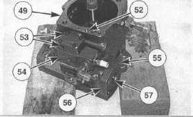
6.
Install O-ring seal (59) on cover (58). Install cover (58)
in pump housing (49), and install the four bolts. Tighten
the bolts to a torque of 25 N m (18.4 lb-ft).
7.
Position servo piston assembly (56) in the pump
housing, and install four bolts (55). Tighten the bolts to
a torque of 25 N m (18.4 lb-ft).
8.
Position the gasket and directional control valve (54) on
the pump housing, and install five bolts (53). Tighten
the bolts to a torque of 10 N m (7.4 lb-ft).
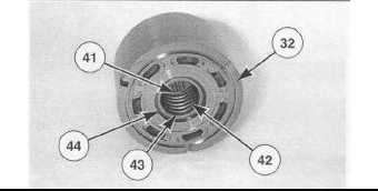
9.
Install shim (41), spring (42) and shim (43) in cylinder
block assembly (32).
10. Put cylinder block assembly (32) in a press. Install a
suitable piece of square steel stock against spring (42).
Put a slight compression on spring (42) with the press.
Install retaining ring (44), and slowly release the spring
compression.
14-47