TM 5-3895-383-24
8.
Adjust high amplitude relief valve (4) in the following
steps:
a.
Stop the engine.
b.
Remove the cap of high amplitude relief valve (4).
c.
Remove the high pressure relief valve cartridge.
Install the cap of high pressure relief valve (4). This
will ensure that the oil does not leak while
adjustments are made to the cartridge and the spring.
d.
Hold the high pressure relief valve cartridge in a
bench vise. Secure the high pressure relief valve
cartridge by clamping on collar (6).
e.
Loosen lock screw (7) with a 3 mm Allen wrench.
f.
Use a 5 mm wrench and adjust the pressure by
turning spindle (5). Turn the spindle clockwise in
order to increase the pressure. Turn the spindle
counterclockwise in order to decrease the pressure.
One full rotation of spindle (5) equals 4400 kPa (638
psi).
g.
Tighten lock screw (7).
h.
Remove the high pressure relief valve from the vise.
i.
Reinstall the high pressure relief valve cartridge.
Install the cap of high pressure relief valve (4) and
torque to specifications.
9.
Repeat Step 5.
10.
Stop the engine.
NOTE: After five minutes of operation, when the drum is
on tires, the vibratory operating pressure should
decrease to a maximum of 10340 kPa (1500 psi).
If continued high pressure is observed, a problem
may exist with the vibratory drive mechanism.
Low Amplitude
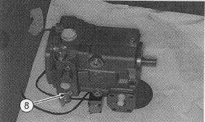
Illustration 51
Vibratory Pump
(8) Test port.
1.
Make sure that the parking brake is applied. Ensure
that the propel control lever is in the STOP position.
2.
Connect a 60000 kPa (8700 psi) pressure gauge to
relief valve test port (8).
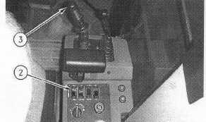
Illustration 52
Control Console
(2) Vibratory amplitude control. (3) Vibratory ON/OFF control.
3.
Move vibratory amplitude control (2) to the LOW
AMPLITUDE position.
4.
Install the Multitach in order to measure the engine rpm.
Install 4C-6500 Digital Thermometer into the hydraulic
oil tank. Start the machine and run the machine at high
idle (2350 ± 50 RPM) until the hydraulic oil temperature
reaches 38C (100F).
11-49