TM 5-3895-383-24
Vibratory System ON
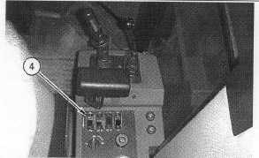
Illustration 46
Control Console
(4) Amplitude selector.
1.
Place the amplitude selector (4) in the LOW
AMPLITUDE position.
2.
With the engine at high idle (2350 ± 50 RPM), activate
the vibratory system. Observe the vibratory charge
pressure at pressure test port (1). The vibratory charge
pressure should be 130 ± 70 kPa (19 ± 10 psi) lower
than the normal operating pressure that was measured
in "Vibratory System OFF".
3.
Place the amplitude selector (4) in the HIGH
AMPLITUDE position. Repeat Step 2 again. The
charge pressure should have the same value. This step
verifies the movement of the spool in the flushing valve.
NOTE:
The vibratory charge pressure is controlled by the
flushing valve which is located in the motor. If the
charge pressure at test port (1) does not decrease
from the pressure that was recorded in "Vibratory
System OFF", a problem may exist with the
flushing valve and/or the adjustment of the charge
relief valve. The vibratory charge pressure should
be 130 ± 70 kPa (19 ± 10 psi) lower than the
pressure that was recorded in "Vibratory System
OFF". If the pressure decreases too much,
excessive case leakage may exist or the flushing
valve may be improperly shimmed. The nominal
stack height of the shims should be 6.5 mm (0.26
inch). The Testing and Adjusting Vibratory Motor
Case Drain Flow - Test and Adjust should be
performed if the charge pressure is too low.
4.
Stop the vibratory system and stop the engine. Remove
all tooling.
Main Relief Valve - Test and Adjust
SMCS Code: 5069-025-PX; 5069-081-PX
Table 8
Required Tools
Part Number
Description
Qty
4C-6500
Digital Thermometer
1
4C-4892
ORFS Fittings Group
1
9U-7400
Multitach
1
Personal injury or death can result from sudden machine
movement.
Sudden movement of the machine can cause injury to
persons on or near the machine.
To prevent injury or death, make sure that the area around
the machine is clear of personnel and obstructions before
operating the machine.
NOTICE
Care must be taken to ensure that fluids are contained
during performance of inspection, maintenance, testing,
adjusting and repair of the product. Be prepared to collect
the fluid with suitable containers before opening any
compartment or disassembling any component containing
fluids.
Refer to Special Publication, NENG2500, "Caterpillar Tools
and Shop Products Guide" for tools and supplies suitable
to collect and contain fluids on Caterpillar products.
Dispose of all fluids according to local regulations and
mandates.
NOTICE
To avoid damage to the vibratory system during testing,
always perform the testing with the vibratory drum on top
of tires or on loose dirt. Tires will simulate a non-
compacted soil condition.
Never operate the vibratory system when the machine is
on concrete.
11-47