TM 5-3895-383-24
Piston Motor Case Drain Flow - Test and Adjust
SMCS Code: 5651-025-FW; 5651-081-FW
Table 11
Required Tools
Pad Number
Description
Qty
4C-8689
Flow Meter
1
8C-6874
Adapter
2
6V-8942
Adapter
2
6V-8556
Nut
2
7X-1449
Orifice Coupling
1
7X-1447
Orifice Coupling
1
9X-2350
Hose
36 inches
4C-6500
Digital Thermometer
1
Personal injury or death can result from sudden machine
movement.
Sudden movement of the machine can cause injury to
persons on or near the machine.
To prevent injury or death, make sure that the area around
the machine is clear of personnel and obstructions before
operating the machine.
NOTICE
Care must be taken to ensure that fluids are contained
during performance of inspection, maintenance, testing,
adjusting and repair of the product. Be prepared to collect
the fluid with suitable containers before opening any
compartment or disassembling any component containing
fluids.
Refer to Special Publication, NENG2500, "Caterpillar Tools
and Shop Products Guide" for tools and supplies suitable
to collect and contain fluids on Caterpillar products.
Dispose of all fluids according to local regulations and
mandates.
NOTICE
To avoid damage to the vibratory system during testing,
always perform the testing with the vibratory drum on top
of tires or on loose dirt. Tires will simulate a non-
compacted soil condition.
Never operate the vibratory system when the machine is
on concrete.
NOTICE
If a testing time longer than three (3) minutes is required,
rotate the drum periodically in order to lubricate the
eccentric weight shaft bearings.
NOTE: The hydraulic oil temperature should be at least
38° C (100° F).
1.
Make sure that the parking brake is applied. Make sure
that the propel control lever is in neutral. Make sure that
the vibratory on/off control on the propel control lever is
in the OFF position.
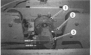
Illustration 57
End of Drum
(1) Vibratory motor. (2) Drain line. (3) Flushing valve.
2.
Disconnect drain line (2) from vibratory motor (1).
3.
Install 90 cm (36 in) of 9X-2350 Hose and 4C-8689 Flow
Meter (5) between vibratory motor (1) and drain line (2).
4.
Install 4C-6500 Digital Thermometer into the hydraulic
oil tank.
5.
Move the vibratory amplitude control to the LOW
AMPLITUDE position.
6.
Start the engine and run the machine at high idle until
the hydraulic oil temperature reaches 38 C (100F).
Engine speed should be 2350 50 rpm.
11-53