TM 5-3895-382-24
NOTICE
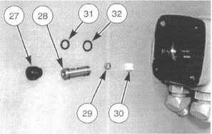
O-ring seals (31) and (32) are different sizes. Note the
location of the O-ring seals on the check ball seat prior to
removal. Do not mix during assembly.
22.
Remove check ball (29) and check ball retainer (30)
from the control housing. Remove O-ring seals (31) and
(32) from check ball seat (28). Inspect the O-ring seals
for damage or wear and replace if necessary.
NOTE:
The following steps are for assembly of the
steering control unit (SCU).
NOTICE
Be sure all parts of the steering control unit (SCU) are
clean and free of dirt and debris. Do not use a cloth or
paper towel to dry parts. Lint or other material can get
into the hydraulic system and cause damage to
components. Replace any parts that have scratches or
burrs that could result in leakage.
23.
Install check ball retainer (30) in control housing (12).
Be sure the retainer is straight and not tilted in the bore.
Install check ball (29).
24.
Put a thin coat of 1U-6396 Assembly Compound on O-
ring seals (31) and (32) and check ball seat (28). Install
the O-ring seals in their original location on the check
ball seat. Using a 1/8" -24 machine screw, install the
check ball seat in the center housing.
25.
Install set screw (27) and tighten to a torque of 11 N· m
(100 lb-in). After installation, the set screw should be
slightly below the outside surface of the center housing.
26.
Put a thin coat of clean hydraulic oil on control spool
(19) and control housing sleeve (20). Install the control
spool in the control housing sleeve. The spool should
turn freely in the sleeve. Put the spring slots in each
component in alignment. Some spool and sleeve sets
may have alignment marks on them. In this case, align
the marks. Install centering spring kit (21). Be sure the
springs are centered. Install pin (18) that holds control
spool (19) and control housing sleeve (20) together.
The pin should be flush on each side of the sleeve after
installation.
NOTICE
When spool and sleeve assembly (11) is installed In the
control housing, be sure it is not tilted out of position. The
assembly should be pushed gently Into place with a slight
rotating action, keeping pin (18) nearly horizontal. The
spool and sleeve assembly should be installed until it is
flush with the meter end of the housing (side with fourteen
holes in the end). Be sure the spool and sleeve assembly
turns freely in the center housing.
27.
Put the center housing in a vertical position. Install two
bearing races (16) and needle thrust bearing (17).
28.
Assemble gland bushing (23). Install dust seal (24) in
seal gland bushing (25) with the flat or smooth side of
the seal facing the bushing. Turn the seal gland
bushing over Install quad ring seal (26) in the seal gland
bushing. Smooth the seal in place with your finger. Do
not use a seal that falls freely into the pocket in the
bushing.
29.
Install gland bushing (23) over the control spool with a
twisting motion. Use a soft faced hammer to seat the
gland bushing against bearing race (16). Install
retaining ring (22). Be sure the retaining ring is properly
seated.
30.
Put the steering control unit (SCU) in a vertical position
with the steering column end facing down. Install O-ring
seal (10) in control housing (12).
31.
Install spacer plate (9). Be sure the holes in the spacer
plate align with the tapped holes in the control housing.
Put pin (18) in a horizontal position in the control
housing. Install drive (8). Be sure the slot in drive (8)
engages with pin (18).
16-19


