TM 5-3895-382-24
Installation Procedure
Table 10
Required Tools
Tool
Part
Number
Part Description
Qty
1U-9169
Valve Guide Driver
1
A
9U-6220
Stop Collar
1
NOTICE
Keep all parts clean from contaminants.
Contaminants may cause rapid wear and shortened
component life.
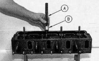
Illustration 78
1.
Position the valve guide. Carefully tap the valve guide
in order to start the installation. Use Tool (A) and Tool
(B) to seat the valve guide in the cylinder head
assembly.
2.
Check the protrusion of the inlet valve guide. The inlet
valve guide should protrude 15.10 mm (.595 inch)
above the cylinder head assembly.
3.
Repeat the procedure for the remaining valve guides.
End By:
a.
Install the inlet valves and the exhaust valves. Refer
to Disassembly and Assembly, "Inlet and Exhaust
Valves - Remove and Install”.
Inlet and Exhaust Valve Seat Inserts - Remove and
Install
SMCS Code: 1103-010
Removal Procedure
Table 11
Required Tools
Tool
Part
Number
Part Description
Qty
9U-6396
Insert Valve Seat Extractor
1
9U-6397
Exhaust Valve Seat
Extractor
1
A
9S-3095
Channel
1
Start By:
a.
Remove the inlet valves and the exhaust valves.
Refer to Disassembly and Assembly, "Inlet and
Exhaust Valves - Remove and Install".
NOTICE
Keep all parts clean from contaminants.
Contaminants may cause rapid wear and shortened
component life.
Illustration 79
7-34