
TM 5-3895-379-23-1
0207
ADJUSTMENT
NOTE
The vibratory system can be activated at various speeds ranging from 10% to 100% of
the propel control lever stroke. This activation will occur when the vibratory control switch
is in the AUTO position and the vibratory on/off switch is in the ON position.
Separate adjustments can be made for both forward and reverse activation of vibratory
system.
1.
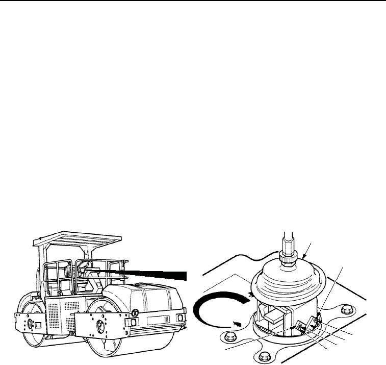
Lift boot (Figure 1, Item 1) to expose cams (Figure 1, Item 3).
2.
Start engine (TM 5-3895-379-10).
NOTE
Cam toward front of roller controls vibratory system when roller is traveling in reverse
direction. Cam toward rear of roller controls vibratory system when roller is traveling in forward
direction.
3.
Loosen cam adjustment screws (Figure 1, Item 2) and adjust cams (Figure 1, Item 3) until the vibratory system
is activated at desired travel speed (usually 40 to 70% of full speed).
4.
Tighten cam adjustment screws (Figure 1, Item 2).
1
ADJUSTS
REVERSE
VIBRATION
2
3
ADJUSTS
2
3
FORWARD
VIBRATION
M0376SWR
Figure 1. Engagement Stops Adjustment.
5.
Turn engine off (TM 5-3895-379-10).
NOTE
If cams cannot be adjusted to automatically start vibration, engagement switches may need
adjustment. If you have adjusted cams and vibration startup is OK, skip Steps (6) through
(13).
6.
Remove two screws (Figure 2, Item 1) and washers (Figure 2, Item 11) from operator station
(Figure 2, Item 4).
7.
Remove seven screws (Figure 2, Item 1) and washers (Figure 2, Item 2) from operator station
(Figure 2, Item 4).
03/15/2011Rel(1.8)root(maintwp)wpno(M00145)