
TM 5-3895-379-23-1
0174
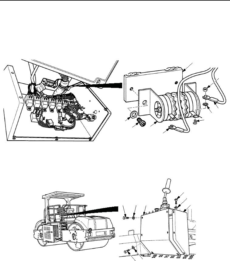
INSTALLATION
1.
Install two new lockwashers (Figure 3, Item 4) and wires (Figure 3, Items 3 and 6) on starting aid resistor
(Figure 3, Item 7) with two screws (Figure 3, Item 5) and new locknuts (Figure 3, Item 2).
2.
Install starting aid resistor (Figure 3, Item 7) on panel assembly (Figure 3, Item 1) with two screws
(Figure 3, Item 8) and washers (Figure 3, Item 9).
1
2
3
4
5
9
7
8
6
M1106SWR
Figure 3. Starting Aid Resistor Installation.
3.
Install panel assembly (Figure 4, Item 3) on operator station (Figure 4, Item 4) with two washers
(Figure 4, Item 5), seven washers (Figure 4, Item 2), and nine screws (Figure 4, Item 1).
1
2
1
2
3
4
5
1
M0928SWR
Figure 4. Starting Aid Resistor Installation.
END OF TASK
03/15/2011Rel(1.8)root(maintwp)wpno(M00112)