
TM 5-3895-379-23-1
0175
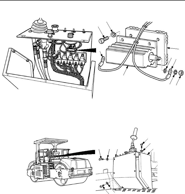
INSTALLATION - Continued
2
1
3
9
45
8
7
6
M1105SWR
Figure 3.
Fuel Solenoid Resistor Installation.
3.
Install panel assembly (Figure 4, Item 3) on operator station (Figure 4, Item 4) with two washers
(Figure 4, Item 5), seven washers (Figure 4, Item 2), and nine screws (Figure 4, Item 1).
1
2
1
2
3
4
5
1
M0931SWR
Figure 4.
Fuel Solenoid Resistor Installation.
END OF TASK
03/15/2011Rel(1.8)root(maintwp)wpno(M00113)