
TM 5-3895-379-23-1
0174
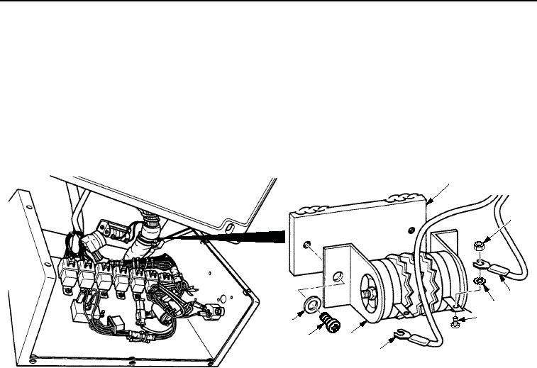
REMOVAL - Continued
4.
Remove two screws (Figure 2, Item 8), washers (Figure 2, Item 9), and starting aid resistor (Figure 2, Item 7)
from panel assembly (Figure 2, Item 1).
NOTE
Tag and mark all wires prior to removal.
5.
Remove two locknuts (Figure 2, Item 2), wires (Figure 2, Items 3 and 6), lockwashers (Figure 2, Item 4), and
screws (Figure 2, Item 5) from starting aid resistor (Figure 2, Item 7). Discard locknuts and lockwashers.
1
2
3
4
5
9
7
8
6
M0927SWR
Figure 2. Starting Aid Resistor Removal.
END OF TASK
03/15/2011Rel(1.8)root(maintwp)wpno(M00112)