
TM 5-3895-379-23-1
0166
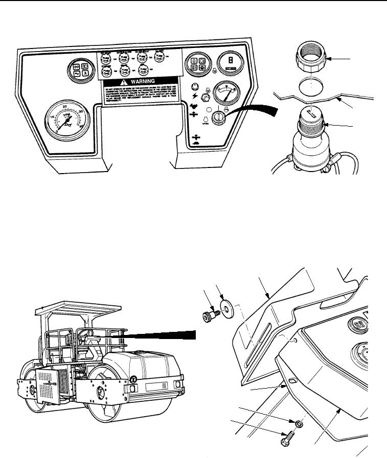
INSTALLATION - Continued
1
2
3
STEERING WHEEL SHOWN REMOVED FOR CLARITY
M1223SWR
Figure 5. Engine Start Switch Installation.
6.
Install instrument box assembly (Figure 6, Item 4) on operator station (Figure 6, Item 7) with three washers
(Figure 6, Item 6) and screws (Figure 6, Item 5).
7.
Install vandal guard (Figure 6, Item 3) on instrument box assembly (Figure 6, Item 4) with two washers
(Figure 6, Item 2) and shoulder screws (Figure 6, Item 1).
3
2
1
7
6
5
4
M0897SWR
Figure 6. Engine Start Switch Installation.
END OF TASK
03/15/2011Rel(1.8)root(maintwp)wpno(M00104)