
TM 5-3895-379-23-1
0166
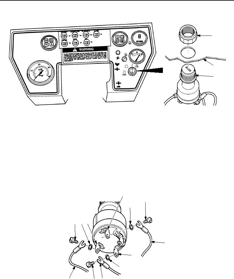
REMOVAL - Continued
1
2
3
STEERING WHEEL SHOWN REMOVED FOR CLARITY
M0895SWR
Figure 2. Engine Start Switch Removal.
NOTE
Tag and mark all wires prior to removal.
6.
Remove screw (Figure 3, Item 6), wire (Figure 3, Item 7), and lockwasher (Figure 3, Item 5) from START
terminal (Figure 3, Item 4). Discard lockwasher.
7.
Remove screw (Figure 3, Item 1), wire (Figure 3, Item 12), and lockwasher (Figure 3, Item 2) from BATTERY
terminal (Figure 3, Item 3). Discard lockwasher.
8.
Remove screw (Figure 3, Item 11), wire (Figure 3, Item 10), and lockwasher (Figure 3, Item 9) from RELAY
terminal (Figure 3, Item 8). Discard lockwasher.
4
6
5
23
1
7
8
9
12
11 10
M0896SWR
Figure 3. Engine Start Switch Removal.
END OF TASK
03/15/2011Rel(1.8)root(maintwp)wpno(M00104)