
TM 5-3895-379-23-1
0081
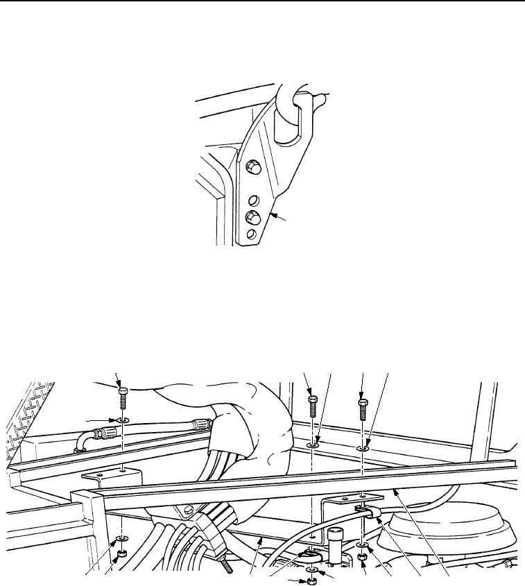
INSTALLATION - Continued
7.
Remove lifting device from rear engine lifting plate (Figure 9, Item 1).
1
M0065SWR
Figure 9. Rear Engine Mount Installation.
8.
Install upper cross brace (Figure 10, Item 10) on upper frame assembly (Figure 10, Item 5) with four washers
(Figure 10, Item 4), screws (Figure 10, Item 1), two clips (Figure 10, Item 6), four washers (Figure 10, Item 4),
and nuts (Figure 10, Item 7).
9.
For CB534B Roller, install clip (Figure 10, Item 9) on upper cross brace (Figure 10, Item 10) with washer
(Figure 10, Item 3), screw (Figure 10, Item 2), washer (Figure 10, Item 3), and nut (Figure 10, Item 8).
2
3
1
4
1
4
4
7
10
9
8
3
7
4
6
5
I0066SWR
Figure 10.
Rear Engine Mount Installation.
END OF TASK
03/15/2011Rel(1.8)root(maintwp)wpno(M00020)